


Solenoid Valve Types - A Comprehensive Guide
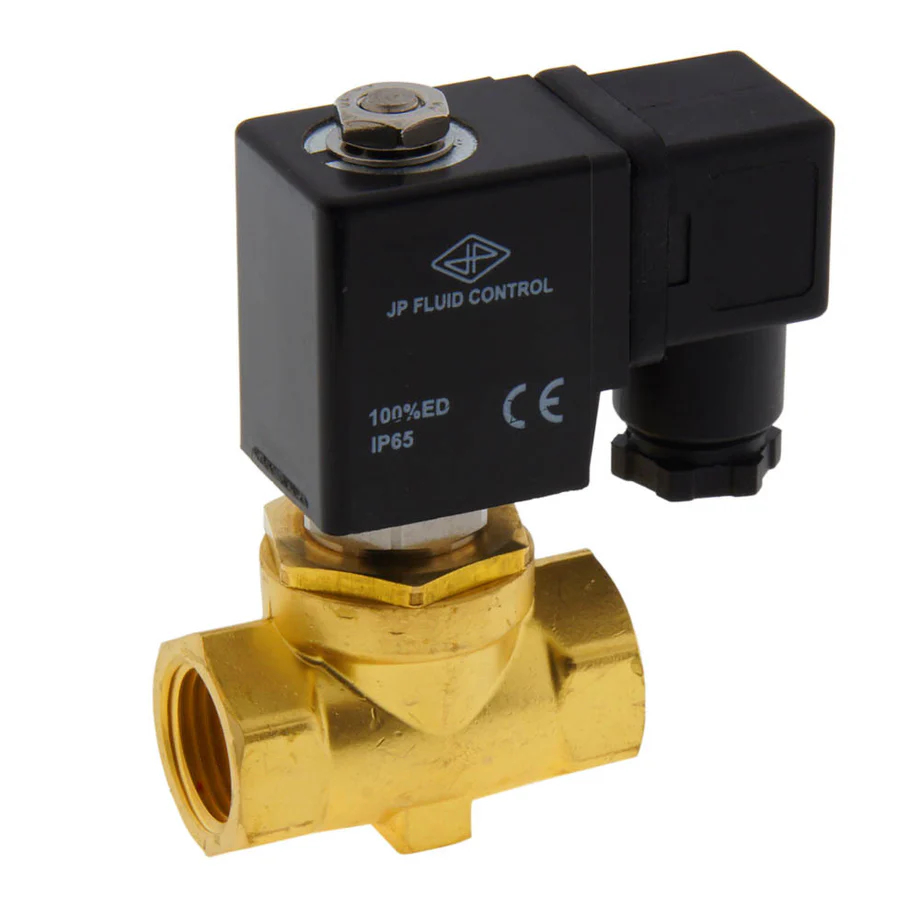
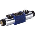
Figure 1: 2/2-way solenoid valve
A solenoid valve is an electrically controlled valve that allows or prevents media flow through it. A solenoid valve works by having a plunger move up and down based on the magnetic field generated by the electrical solenoid. The plunger either opens or closes the orifice that the media flows through. Different designs, construction materials, and circuit functions allow solenoid valves to be used in various applications. Since they are electrically controlled, they can be controlled remotely and automatically. They are commonly found in water treatment, automotive, food processing, and other industrial applications. This article is a complete guide on solenoid valves.
Table of contents
- How does a solenoid valve work?
- Solenoid valve types
- Normally open vs normally closed solenoid valves
- 2-way solenoid valve
- 3-way solenoid valve
- Housing material
- Sealing material
- Solenoid valve approvals
- Special solenoid valve features
- Selection criteria
- Other solenoid valve applications
- FAQs
View our online selection of solenoid valves!
How does a solenoid valve work?
A solenoid valve consists of two main components: a solenoid and a valve body. A solenoid has an electromagnetically inductive coil around an iron core at the center called the plunger. AC coils have a shading ring, which prevents vibration and humming.
At rest, the valve can be normally open or normally closed. In the de-energized state, a normally closed valve is closed. When current flows through the solenoid, the coil is energized, creating a magnetic field. This creates a magnetic attraction with the plunger, moving it and overcoming the spring force. The plunger lifts so the seal opens the orifice, allowing the media to flow through the valve. A normally open solenoid valve works oppositely. To learn more about individual components, read our solenoid valve parts article.
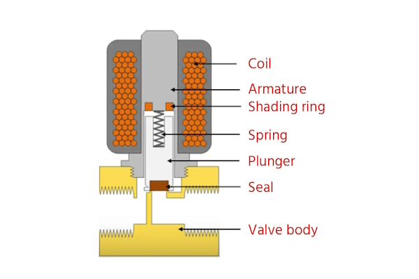
Figure 2: Components of a solenoid valve
Solenoid valve types
Direct acting
A direct-acting solenoid valve uses the solenoid to open or close without differential pressure. These valves are often used to control the flow of gas or liquid in a system. Direct-acting solenoid valves have the fastest operation, are reliable, and have a compact design.
Indirect acting
Indirect-acting solenoid valves, whether servo-operated or pilot-operated, operate using pressure differences. They require a minimum pressure differential of about 0.5 bar. These valves include a diaphragm with a small hole that allows flow from the inlet to the outlet when the solenoid is energized and the pressure drops. This system amplifies the pressure, allowing a small solenoid to control a large flow rate. Indirect solenoid valves are used in applications with sufficient pressure differential and high desired flow rates, and they only allow media flow in one direction.
Semi-direct acting
Semi-direct acting solenoid valves blend the features of direct and indirect valves, enabling operation from zero bar while managing high flow rates. These valves resemble indirect valves with a movable membrane, a small orifice, and pressure chambers on both sides, but the solenoid plunger is directly connected to the membrane. When the plunger lifts, it directly opens the valve and a second orifice, causing the pressure to drop and the membrane to lift. This results in a valve operating from zero bar and managing significant flow rates. These semi-direct operated valves, also known as assisted-lift solenoid valves, often have more powerful coils than indirect-operated valves.
Normally open vs normally closed solenoid valves
Normally open solenoid valve
A normally open (NO) solenoid valve is open when de-energized, allowing the media to flow through it. When current is sent to the coil, it creates an electromagnetic field that forces the plunger downwards, overcoming the spring force. The seal sits in the orifice and closes it, preventing media from flowing through the valve.
Figure 3 shows the operating principle of a normally open solenoid valve in the de-energized and energized states. A normally open solenoid valve is ideal for applications that require the valve to be open for long periods of time, as this is more energy efficient. They can also be used for safety reasons if the application requires the valve to be open with no power (e.g., to prevent overpressure).
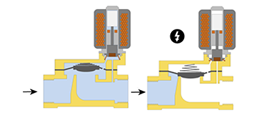
Figure 3: Operating principle of normally open solenoid valve: de-energized (left) and energized (right).
Normally closed solenoid valve
A normally closed (NC) solenoid valve is closed when de-energized, which prevents the media from flowing through it. When current is sent to the coil, it creates an electromagnetic field that forces the plunger upwards, overcoming the spring force. This unseats the seal and opens the orifice, allowing the media to flow through the valve.
Figure 4 shows the operating principle of a normally closed solenoid valve in the de-energized and energized states. A normally closed solenoid valve is ideal for applications that require the valve to be closed for long periods of time, as this is more energy efficient. They can also be used for safety reasons if the application requires the valve to be closed without power (e.g., gas appliances).
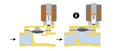
Figure 4: Operating principle of normally closed solenoid valve: de-energized (left) and energized (right).
Bi-stable solenoid valve
A bi-stable or latching solenoid valve can be switched by a momentary power supply. When de-energized, the valve stays in the position it switched to. Therefore, it is not normally open or closed, as it stays in the current position when no power is applied. They accomplish this by using permanent magnets rather than a spring. This gives the benefit of reduced power consumption.
2-way solenoid valve
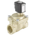
2-way solenoid valves have two ports, an inlet, and an outlet, and are used to allow or block flow. The flow direction through the valve is critical to ensure proper operation. Typically, an arrow indicates the flow direction on the body of the valve.
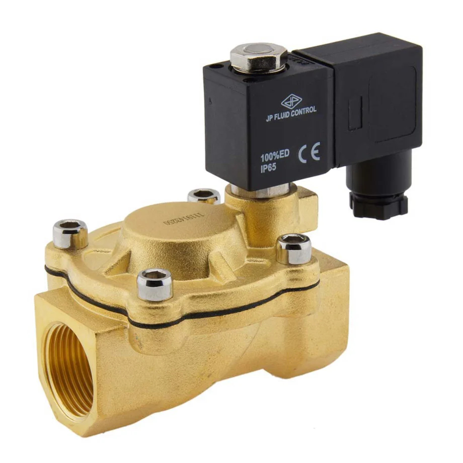
Figure 5: JP Fluid Control 2 way solenoid valve (type CM-IA).
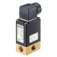
3-way solenoid valve
A 3-way solenoid valve usually features three ports, each serving a distinct purpose: one for the inlet, one for the outlet, and one depending on the valve's configuration and application (exhaust, return, another inlet, or another outlet). Here are the common designations for these ports:
- P (pressure) port or inlet port: This is where the pressurized fluid or gas enters the valve.
- A (actuator) port or outlet port: This is the working port connected to the device or actuator that the valve is intended to control, such as a single-acting pneumatic cylinder or a process line.
- E (exhaust) port or R (return) port: When the valve is switched to the exhaust position, this port vents the fluid or gas from the actuator or device back to the atmosphere or a reservoir. Depending on the valve's configuration and application, this port might also serve as an alternative inlet or outlet in some systems.
The specific function of the ports depends on the state of the solenoid valve (energized or de-energized) and the design (normally closed or normally open).
- Normally closed (NC): When the valve is de-energized, the P port is closed, and no flow is allowed from the inlet to the outlet. The A port is typically connected to the E or R port, allowing the actuator to exhaust. When energized, the valve opens the flow from the P port to the A port and closes off the E or R port.
- Normally open (NO): When the valve is de-energized, the P port opens to the A port, allowing flow from the inlet to the outlet. The E or R port is closed. When energized, the valve switches to close the flow from P to A and opens the connection between A and E or R, allowing the actuator to exhaust.
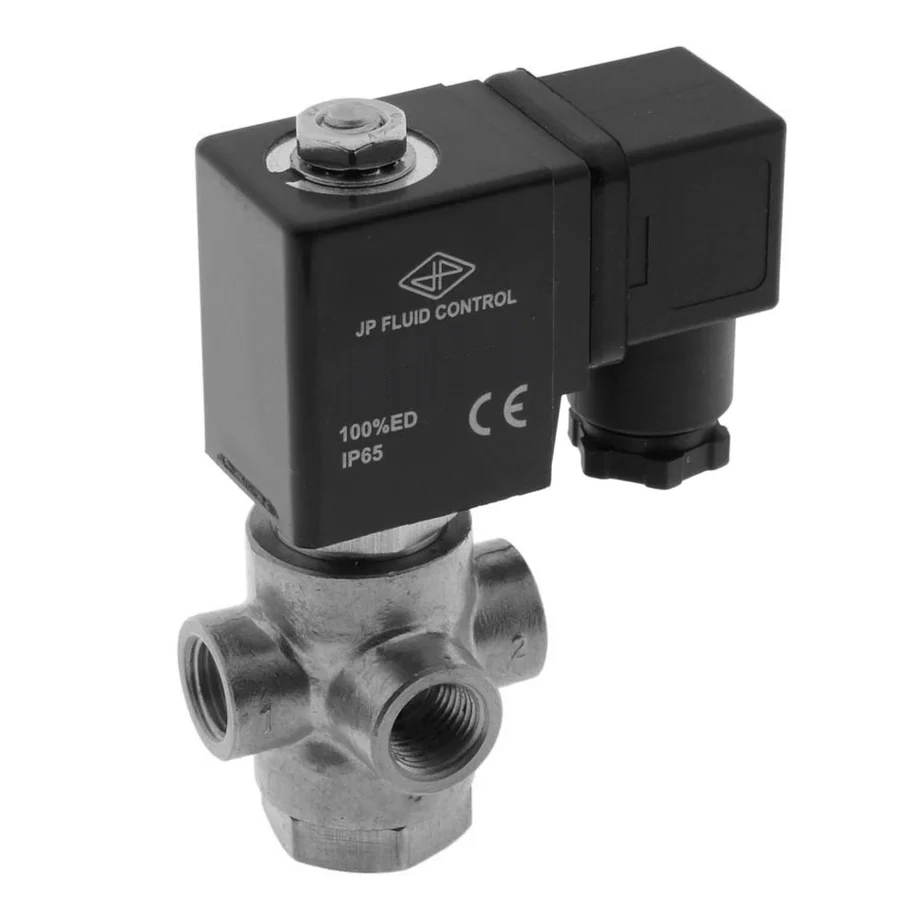
Figure 6: JP Fluid Control 3 way solenoid valve (type TP).
Housing material
The solenoid valve's housing and body material must be compatible with the media. Common options are brass, stainless steel, PVC, aluminum, and cast iron. See our quick guide below, but refer to our housing material guide and media compatibility chart for more information.
- Brass: Brass has good corrosion resistance with neutral media, such as water.
- Stainless steel: Stainless steel has good chemical, temperature, and pressure resistance.
- PVC: PVC and polyamide are commonly used because they are cost-efficient. They are also used in high-end applications with aggressive chemicals.
- Aluminum: Aluminum's lightness, strength, and thermal properties make it a cost-effective and reliable choice for solenoid valve housings.
- Cast iron: Cast iron provides a strong, wear-resistant, cost-effective housing for solenoid valves, with added vibration damping suitable for tough industrial applications.
Sealing material
The solenoid valve's sealing material must also be compatible with the media. Common options include NBR, EPDM, FKM (Viton), and PTFE (Teflon). See our quick guide below, but refer to our seal material guide and media compatibility chart for more information.
- NBR: NBR seals have excellent oil and fuel resistance, making them ideal for petroleum-based applications.
- EPDM: EPDM seals have great resistance to weathering, ozone, and steam, suiting them for outdoor and hot water applications.
- FKM (Viton): FKM seals are highly chemical and heat resistant, perfect for harsh chemical and high-temperature environments.
- PTFE (Teflon): PTFE seals have exceptional chemical inertness and a wide temperature range, making them versatile for aggressive media and extreme conditions.
Solenoid valve approvals
Certain approvals for the valve may be needed. Having a valve with a specific authorization ensures it meets the application's demands. Common approvals are:
- UL/UR: Underwriters Laboratories inspects and certifies products with respect to their safety
- Drinking water: Ensures it is suitable for drinking water purposes. For more information, refer to our drinking water application page or view our water solenoid valves article.
- FDA: US Food and Drug Administration
- ATEX version: ATEX certification is provided for explosion protection. For more information, refer to ATEX Directives for valves and fittings.
- CE certification: CE certification signifies conformity with high safety, health, and environmental protection requirements for all products in the European Economic Area. For more information, refer to our CE certification page.
- Gas version: Valves for gas applications have DVGW approval for use in gas-burning appliances as automatic shut-off valves. For more information, refer to our Gas Approval Regulation page.
- IP rating: The IP rating of a valve explains its protection to dust and water. For more information, refer to our IP rating page.

Figure 7: Approvals and certifications.
Special solenoid valve features
- Electric power reduction: The rated voltage is supplied to the valve for a short period of time to actuate the valve, then it is reduced to a holding voltage that is strong enough to hold the valve in that position while reducing power consumption.
- Latching: Latching or pulse coil version provides a solution for applications with low-frequency switching. The valve is energized by a short electric pulse to move the plunger. A permanent magnet is then used to keep the plunger in that position with no additional spring or magnetic field. This lowers power consumption and heat development in the valve.
- High Pressure: High-pressure versions are designed for up to 250 bar pressure requirements.
- Manual override: Optional manual override feature provides better safety and convenience during commissioning, testing, maintenance, and in case of a power failure. In some versions, the valve cannot electrically actuate when the manual control is locked.
- Media separation: A media separation solenoid valve's design allows isolation of the media from the valve’s working parts, making it a good solution for aggressive or slightly contaminated media.
- Vacuum: Valves that do not require a minimum pressure differential are suitable for rough vacuums. Universal direct-acting or semi-direct-acting solenoid valves are well suited for these applications. Special vacuum versions are available for more stringent leakage rate requirements.
- Adjustable response time: The time it takes the valve to open or close can be adjusted, typically by rotating screws on the valve’s body. This feature can help prevent water hammer.
- Position feedback: The switching status of a solenoid valve can be indicated with an electrical or optical position feedback as a binary or NAMUR signal. NAMUR is a sensor output that indicates the on or off state of the valve.
- Low noise: Valves have a damped design to reduce the noise during the closing of the valve.
Selection criteria
It is essential to understand your application before selecting a solenoid valve. Some important selection criteria are as follows:
- Housing material: Determine valve housing material based on the chemical properties and temperature of the media and the environment the valve is in. Common options are brass, stainless steel, PVC, aluminum, and cast iron.
- Connection size: Ensure the solenoid valve's port sizes are the same as what the valve will connect to.
- Connection type: Connection types range from flanged, threaded, welded, push-in, and more.
- De-energized state: Determine if the application needs a normally open, normally closed, or bi-stable valve function.
- Voltage: Determine the power supply's voltage and select a solenoid valve with a corresponding solenoid.
- Seal material: Seal material should be selected based on the chemical properties and temperature of the media. Common options include NBR, EPDM, FKM (Viton), and PTFE (Teflon). Refer to select the right seal material for your solenoid valve for quick reference on chemical resistance of seal materials.
- Operation: Solenoid valves can be direct, indirect, or semi-direct. Read the solenoid valve types section above to learn more.
- Pressure: The valve must be able to withstand the maximum pressure required for the application. It is equally important to note the minimum pressure as a high-pressure differential can cause the valve to fail.
- Connector: A solenoid connector is a device that plugs into a solenoid valve to supply it with electricity, and it helps protect the connections from dirt and water.
- Temperature: Ensure that the valve materials can withstand the application's minimum and maximum temperature requirements. Temperature consideration is also essential to determine valve capacity as it affects the viscosity and flow of the fluid.
- Response time: The response time of a valve is the time needed for a valve to go from the open to the closed position or vice versa. Small direct-acting solenoid valves react much quicker than semi-direct or indirect-acting valves.
- Approvals: Ensure that the valve is appropriately certified depending upon the application.
- Degree of protection: Ensure the valve has the appropriate IP rating for dust, liquid, moisture, and contact protection.
Other solenoid valve applications
Common domestic and industrial solenoid valve applications include:
- Refrigeration systems use solenoid valves to reverse the flow of refrigerants. This helps in cooling during summer and heating during winter.
- Irrigation systems use solenoid valves with automatic control.
- Dishwashers and washing machines use solenoid valves to control the flow of water.
- Air conditioning systems use solenoid valves to control air pressure.
- Solenoid valves are used in automatic locking systems for door locks.
- Medical and dental equipment use solenoid valves to control the flow, direction, and pressure of the fluid.
- Water tanks use solenoid valves to control the inflow or outflow of water, often in combination with a float switch.
- Car washes to control the water and soap flow.
- Industrial cleaning equipment.
FAQs
What is a solenoid valve used for?
A solenoid valve is used to open, close, mix, or divert media in an application. They are used in a wide variety of applications from dish washers, cars, and irrigation.
How can you tell if your solenoid is bad?
If the solenoid valve fails to open or close, is partially open, makes a humming noise or has a burned-out coil, you need to troubleshoot the valve solenoids. For more information, refer to the troubleshooting guide.
How do I choose a solenoid valve?
Depending upon the media and flow requirement, choose the material, orifice size, temperature, pressure, voltage, response time and certification required for your application.
What is a solenoid?
A solenoid is an electric coil that is wrapped around a ferromagnetic substance (such as iron) that acts as an electromagnet when the current is passed through it.
How does a solenoid work?
When the electric current is passed through the coil, an electromagnetic field is created. This electromagnetic field causes the plunger to move up or down. This mechanism is used by solenoid valves to open or close the valve.


