


What is a Solenoid?
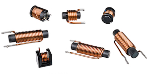
Figure 1: Solenoid coils
A solenoid is a coil of wire that, when energized, generates a magnetic field within its core. When an electric current passes through the solenoid, it creates a magnetic field. This magnetic field moves a ferrous armature, allowing or blocking flow through a solenoid valve. Solenoids are commonly used in various applications, such as controlling fluid flow in hydraulic and pneumatic systems. This article describes the design of a solenoid and how it functions within the design of a solenoid valve.
Table of contents
- Solenoid design and function
- Magnetic field of a solenoid formula
- Solenoid force formula
- Solenoid coil resistance vs temperature
- Solenoid valve force equilibrium
- Solenoid coil applications
- FAQs
View our online selection of solenoid valves!
Solenoid design and function
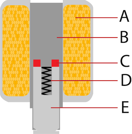
Figure 2: A diagram of a solenoid coil: coil (A), stationary core (B), shading ring (C), spring (D), and armature (E).
As seen in Figure 2, solenoid parts are the following:
- Coil (A): A copper wire tightly wound around the stationary core.
- Stationary core (B): A ferromagnetic cylinder
- Shading ring (C): A shading ring, or shading coil, is a single turn or a few turns of an electrical conductor (copper or aluminum). The shading ring creates a phase shift in the magnetic field, which helps to reduce noise and vibration by ensuring smoother operation of the electromagnetic device.
- Spring (D): A spring that returns the armature to its normal position when the coil is de-energized.
- Armature (E): Part of the stationary core that moves when the coil is energized, also called the solenoid plunger.
Why is there a spring in a solenoid?
The solenoid valve spring serves several important functions:
- Return mechanism: The spring moves the valve to its default position when the solenoid is powered off. With a spring, the valve will close or open, depending on the default position, when the electrical current is turned off.
- Stability and control: An energized solenoid creates an electromagnetic force. The spring provides stability and control for the valve's performance.
- Fail-safe operation: The spring ensures the solenoid valve can maintain safety by closing or opening when no power is supplied.
How does a solenoid work?
A magnetic field is generated when current in a solenoid flows through the coil. The strength of the field is directly proportional to the current, the number of windings, and the permeability of the stationary core's ferromagnetic material. The core acts as a closed path that confines the magnetic field.
The norm is the magnetic field pulls the armature up. However, if the side of the armature near the stationary core is extended, the magnetic field pushes the armature down. In either scenario, a spring is compressed. The armature remains in the position as long as the field remains. When the field dissipates, the spring returns the armature to its original position.
Finally, the shading ring provides a low-impedance path for a high-voltage spike generated when the magnetic field dissipates. This diminishes the voltage spike's magnitude and duration, which protects the circuit.
To understand the complete working principle of solenoid valves, read our solenoid valve overview article.
DC vs AC solenoid coils
The above section explains how a DC solenoid valve works. DC flowing through a solenoid creates a strong magnetic force to overcome the spring force, lifting the armature into the coil. When the coil de-energizes, the spring pushes the armature back down.
AC coils are more complex because AC switches polarity. The current is zero twice per period, making the magnetic force zero. Because the spring force is constantly pushing the armature down, the armature vibrates, creating a humming sound and stressing the components. To solve this issue, a copper shading ring around the armature stores some of the magnetic energy, reducing the vibration.
When the magnetic force overcomes the spring force and the armature is fully lifted, the current running through the coil can be reduced to save energy. DC responds slower than AC because DC provides a steady, unchanging current, which takes longer to build up and reduce magnetic fields. In contrast, AC changes direction rapidly, allowing it to adjust magnetic fields more quickly and efficiently, making AC coils more energy efficient. Read our comparison article to learn more about the advantages and disadvantages of working with DC or AC solenoids.
Magnetic field of a solenoid formula
The magnetic field of a solenoid coil depends on the number of turns per unit length, the strength of the current through the coil, and the solenoid material’s permeability. The formula for measuring the strength of the field is:
Where:
- B: the magnetic flux density
- μ0: The permeability constant which is 12.57 x 10⁻⁷ Hm-1
- I: The current passing through the coil
- N: The number of turns
- L: The coil’s length
Solenoid force formula
The electromagnetic force of a solenoid can be calculated using the following formula:

Where:
- F: solenoid force
- N: the number of coil turns
- I: current (amperes)
- μ0: permeability of free space (approx. 4𝜋 x 10-7 Tm/A)
- A: cross-sectional area of the solenoid
- g: length of gap between coil and iron
Solenoid coil resistance vs temperature
The relationship between solenoid temperature and solenoid resistance is a critical factor in solenoid actuators' and valves' performance and reliability. As the temperature of a solenoid coil increases, the resistance of the solenoid also increases. This relationship is primarily due to the temperature coefficient of resistance of the conductive material, typically copper, used in the coil windings.
As the coil's resistance increases, the current flowing through the coil decreases for a given applied voltage, according to Ohm's Law (V = IR). A reduction in current leads to a decrease in the magnetic force generated by the solenoid, which is a function of the Ampere-Turns (NI) provided by the coil. Consequently, the actuator force of the solenoid diminishes, potentially affecting the performance of the solenoid actuator or valve.
Resistance and temperature formula
When a solenoid is energized, electrical energy is converted into heat due to the power dissipation in the coil, which is proportional to the square of the current (I²R). This self-heating effect, combined with the ambient temperature and the thermal resistance between the coil and its surroundings, increases the coil's temperature.
The resistance of a solenoid coil (R(T)) at a given temperature (T) can be described by the resistance of a solenoid formula:
Where:
- R(T): the resistance at temperature T
- R25: the resistance at 25 °C
- ⍺: the temperature coefficient of resistance for copper (approximately 0.0039 per degree Celsius)
- T: the temperature in degrees Celsius
Example
A solenoid coil with a resistance of 10 ohms at 25 °C will increase to approximately 13.9 ohms at 125 °C. This 39% increase in resistance over a 100 °C rise in temperature illustrates the significant impact that temperature can have on coil resistance.
Practical applications
In practical applications, the solenoid's thermal environment and duty cycle must be considered. Continuous duty applications, where the solenoid is energized for extended periods, can lead to significant temperature rises and increased resistance. Solenoid valves can be rated for 100% duty cycle for applications that operate for extended periods but still these cannot be operated indefinitely. Intermittent duty applications with specified on and off times allow the solenoid to cool down between cycles, mitigating the increase in temperature and its effects on resistance.
High-temperature solenoids
High-temperature solenoids are specifically engineered to operate in environments where standard solenoids would fail due to excessive heat. These solenoids utilize materials with higher thermal resistance and often incorporate advanced cooling mechanisms to manage elevated temperatures.
For instance, high-temperature solenoids may be designed to meet thermal classes such as Class H, allowing for higher operating temperatures without compromising performance. This makes them suitable for applications in harsh thermal environments, ensuring reliable operation even under extreme conditions.
Testing
To ensure optimal performance, measure the coil resistance after a period of operation and compare it to the room temperature resistance. This comparison can help estimate the coil's operating temperature and determine if it is within acceptable limits for the solenoid's design and application.
AC solenoid coil resistance
For AC solenoid coils, the total opposition to current flow is not just due to resistance but also due to inductive reactance. The impedance (Z) of an AC coil is given by:
Where:
- R: the resistance of the coil
- XL: is the inductive reactance, which is given by XL = 2𝜋fL
- f: the frequency of the AC supply
- L: the inductance of the coil
Temperature effects on AC coils
While the resistance (R) of the coil increases with temperature, the inductive reactance (XL) is primarily a function of the coil's inductance and the frequency of the AC supply, and it does not change significantly with temperature. However, the overall impedance (Z) will still be affected by the increase in resistance due to temperature.
Practical Implications
- Current reduction: As the resistance of the AC solenoid coil increases with temperature, the overall impedance increases, leading to a reduction in the current flowing through the coil. However, because the inductive reactance is typically much larger than the resistance, the effect of temperature on the overall impedance is somewhat mitigated compared to a DC coil.
- Magnetic force: The magnetic force generated by an AC solenoid is also a function of the current and the number of turns in the coil. As the current decreases due to increased resistance, the magnetic force will decrease, similar to the behavior in DC solenoids.
- Heating and cooling: AC solenoids may also experience heating due to eddy currents and hysteresis losses in the magnetic core, in addition to the I²R losses in the coil. These additional heating mechanisms can contribute to the solenoid's overall temperature rise.
Solenoid valve force equilibrium
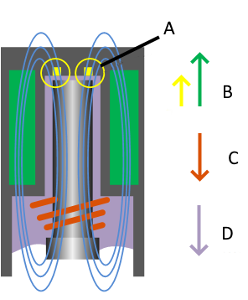
Figure 3: To control flow, a solenoid valve uses a force balance between the coil's magnetic field (B) and the force of the spring (C) and the medium's pressure (D). The magnetic field generated by the shading ring (A) applies to AC coils.
The basic principle of a solenoid valve is a force balance of the magnetic force of the solenoid on one side, and the pressure of the medium and force of the spring on the other side. Calculate the required magnetic force for a direct operated solenoid valve with the following formula:
Where:
- Fs: solenoid force (N)
- p: pressure (Pa) (105 Pa = 1 bar)
- A: orifice (m2)
- Fspring: spring force (N)
Example
A given solenoid provides a force of 15N. To use this solenoid to control a 10 bar pressure differential, the maximum orifice diameter can be calculated.
This formula cannot be used for indirect operated valves. Indirect operated solenoid valves have a smaller orifice and use the pressure of the medium to switch.
Solenoid coil applications
- Locking applications: The magnetic field attracts the plunger within the solenoid, causing it to move and lock the mechanism in place. A spring pushes the plunger back when the current shuts off, releasing the lock. Solenoids can be used in various locking applications, including doors, vending machines, access barriers, and many other security devices.
- Automotive applications: Solenoids are used in various vehicle applications, including shifting the transmission, starting the engine, operating fuel injection systems, locking doors, and actuating valves.
- Medical applications: Solenoids are used in medical applications to control fluid flow, regulate valves in medical gas systems, operate pumps and dispensers, and control the movement of medical equipment.
- Railway applications: In the railroad industry, solenoids are used to operate switches and signals, control brakes, actuate doors and windows, and in diesel engines for fuel injection and exhaust gas recirculation.
- Industrial applications: Solenoids are used in industrial applications to control valves, operate pneumatic and hydraulic systems, actuate clutches and brakes, control the movement of equipment, and in automation, robotics, and manufacturing processes. An actuator of a solenoid is typically a solenoid with a ferromagnetic core.
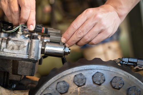
Figure 4: A close-up of a solenoid valve in a tractor transmission system.
FAQs
What is a solenoid valve coil?
A solenoid coil is a tightly wound wire that produces a magnetic field when electricity flows through it and is used to move objects, create electricity or activate a solenoid actuator.
Are solenoids AC or DC?
Solenoids convert AC or DC into linear motion.
How much resistance should a solenoid have?
The resistance of a solenoid varies by design and application, typically ranging from a few ohms to several hundred ohms. Check the manufacturer's specifications for the exact resistance required.
What is solenoid resistance?
Solenoid resistance is the opposition a solenoid coil offers to the flow of electric current, measured in ohms.
How much resistance should a solenoid have?
The resistance of a solenoid varies based on design but typically ranges from a few ohms to several hundred ohms.
What affects the resistance of a solenoid coil?
The resistance of a solenoid coil is affected by wire length, wire gauge, coil temperature, and the material of the wire.
How does temperature affect solenoid resistance?
Solenoid resistance increases with temperature due to the positive temperature coefficient of the wire material, typically copper.


