


Electric Ball Valve Installation
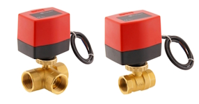
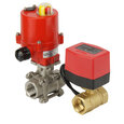
Figure 1: A 3-way (left) and 2-way (right) electric ball valve
The correct installation of an electric ball valve is essential for ensuring the efficient and safe operation of fluid control systems. This article covers:
- The key steps for a successful installation
- The pre-installation procedures
- The installation process
- The post-installation checks
Furthermore, this article describes the tools and techniques required to secure the valve, establish electrical connections, and confirm the system's functionality. The installation process for a BW series JP Fluid Control electric ball valve will be used as an example to provide a clear and practical guide. While this example offers practical steps for installing an electric ball valve, it is crucial to thoroughly read and understand the valve's installation instructions before beginning the procedure.
View our online selection of electric ball valves!
Before installation
The following guidelines are general for any electric ball valve installation:
- Read safety instructions carefully before installation to understand handling and precautions.
- Verify the electric ball valve's suitability for the intended application by checking specifications on the actuator's label (Figure 2), such as pressure rating, temperature range, and media compatibility. Read our article on ball valve markings to understand the information found on the label.
- Choose a dry, sheltered installation location to protect the valve's electric components and ensure easy access for maintenance.
- Depressurize and cool the piping system to prevent injury and create a safe installation environment.
- Inspect pipes for dirt, debris, or corrosion and clean them as necessary to ensure optimal valve performance.
- Install a filter upstream of the valve if the system's media is not clean to prevent damage and blockages.
- Prepare the proper tools and fittings for installation, including an adjustable wrench or multiple wrenches and the correct fittings (threaded or welded) for the system.
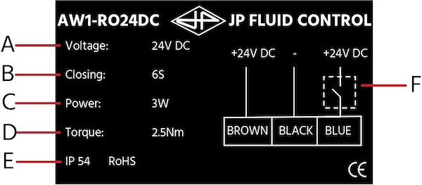
Figure 2: Electric ball valve labels: voltage (A), opening/closing time (B), power (C), torque (D), IP protection (E), wiring diagram (F).
During installation
The following guidelines are for the moment when the valve is ready to be connected to the system:
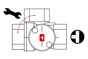
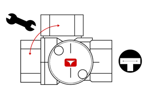
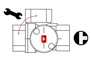
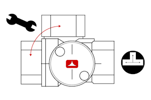
- Ball position: Using a wrench, set the ball to the correct angular position. 2-way ball valves are closed in their standard position. 3-way ball valves can be set up in two different ways by rotating the ball 180°. Table 1 shows how 2-way and 3-way valves can be used.
Table 1: Positioning of the ball in 2 and 3 Way ball valves
| OFF - CLOSE | ON - OPEN | |
| 2 Way | 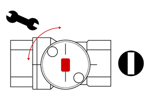 |
 |
3 Way |
 |
 |
 |
 |
-
Connection: An electric ball valve can be connected to a piping system in multiple ways. Figure 3 demonstrates where to tighten a JP Fluid Control ball valve with threaded connections. Tightening in the wrong spot risks damaging the valve. Read our article on ball valve connection types to learn more about the following:
- Threaded
- Welded
- Flanged
- Tri-clamp
- True union
- Actuator positioning: Position the valve so the actuator faces upward, reducing the risk of moisture collecting in the actuator. If this is not possible, the valve can be tilted up to 90°, according to Figure 4.
- Actuator tightening: The ball's position in the valve must be accurate to ensure the actuator can fit snugly to the valve body. Then, the actuator nut can be tightened to a maximum torque. For example, JP Fluid Control electric ball valves can be tightened to a maximum torque of 5 Nm (Figure 5).
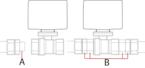
Figure 3: Add thread sealant (A), then tighten the valve connections (B).
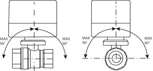
Figure 4: If the electric ball valve cannot be installed so the actuator is upright, it can be rotated by a maximum of 90°.
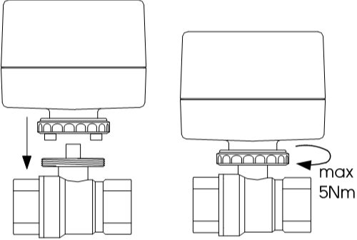
Figure 5: The nut that tightens the actuator to an electric ball valve must not be tightened past its maximum torque.
Wiring the actuator
Wiring the actuator of an electric ball valve correctly is essential for ensuring it operates efficiently and safely. This section provides an overview of the steps involved in wiring the actuator of an electric ball valve.
Understanding the components
Before beginning the wiring process, understand the components of an electric ball valve actuator:
- Electric actuator: The device that physically moves the ball valve to open or close the flow path.
- Power source: Typically, electric actuators require a 24V, 120V, or 240V AC/DC power source.
- Control signal: A signal that tells the actuator when to move, which can be provided by a manual switch, a programmable logic controller (PLC), or a process control system.
- Terminals: Connection points on the actuator for power, ground, and control signals.
Safety precautions
- Ensure the power supply is turned off before wiring to prevent electric shock.
- Verify that the power supply's voltage matches the electric actuator's requirements.
- Use appropriate personal protective equipment (PPE) such as gloves and safety glasses.
Wiring steps
- Identify the wiring diagram: Refer to the manufacturer's wiring diagram for the specific actuator model. This diagram will indicate the correct terminals for power, ground, and control connections. Table 2 demonstrates wiring diagrams for JP Fluid Control electric ball valves.
- Prepare the wires: Strip the ends of the wires to expose the conductive material, ensuring they can make a secure connection with the actuator's terminals.
- Connect the power wires: Attach the power and ground wires to the designated terminals on the actuator. For AC actuators, this will typically involve connecting the live (L) and neutral (N) wires, as well as the ground (G) wire.
- Attach the control signal wires: Connect the control signal wires to the appropriate terminals. The control signal will either open or close the valve, depending on the system's needs.
- Secure the connections: Ensure all terminal screws are tightened to prevent the wires from coming loose due to vibration or other factors.
- Test the actuator: Once all connections are made, turn on the power supply and send a control signal to test the actuator's operation. Observe the movement of the ball valve to confirm that it is responding correctly to the control signal.
- Final inspection: Check all connections for any signs of damage or overheating after initial testing. Confirm that the actuator housing is properly sealed to prevent dust or moisture ingress.
Troubleshooting tips
- If the actuator does not operate as expected, double-check the wiring connections against the wiring diagram.
- Ensure there is no short circuit, and the wires are not crossed.
- Verify that the control signal is being sent and received correctly.
Table 2: Wiring diagrams for JP Fluid Control electric ball valves
| AW1-230AC & AW1-024AC (3-point control) | AW1-R230AC & AW1-R024AC (On/Off control) |
 |
 |
| Never connect Blue & Brown at the same time! Neutral (A), Close (B), and Open (C) | Blue & Brown must be connected to power supply at all times. Neutral (A), Close (B), and Open (C) |
| AW1-024DC & AW1-012DC (3-point control) | AW1-R024DC & W1-R012DC (On/Off control) |
 |
 |
| Never connect Black & Brown at the same time! Minus (D), Close (B), and Open (C) | Black & Brown must be connected to power supply at all times. Neutral (A), Close (B), and Open (C) |
After installation
System checks
- Power cable: Ensure the power cable is positioned so water will not drip into the actuator, as seen in Figure 6.
- Operational testing: Conduct a comprehensive operational test to verify that the ball valve actuates correctly in response to control signals. This should include testing for full open and close positions, as well as any intermediate positions if the actuator is modulating.
- Leak testing: Check for leaks around the valve and actuator. Ensure all seals and gaskets are intact and that there is no leakage of the process fluid.
- Calibration: If the actuator requires calibration, follow the manufacturer's instructions to calibrate the end-stop positions or control signal response.
- Manual override: Test the manual override function to confirm that the valve can be operated manually in case of an electrical failure.
- Safety and emergency shutdown: If the valve is part of a safety or emergency shutdown system, test the fail-safe features to ensure they activate correctly under the appropriate conditions.
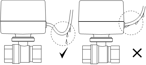
Figure 6: The actuator power cable should be positioned so any moisture does not flow into the actuator's casing.
Documentation
- Record installation details: Document the installation date, model numbers, serial numbers, and any unique installation details for future reference.
- Update system diagrams: Reflect the addition of the new electric ball valve in the system's piping and instrumentation diagrams (P&IDs) and electrical schematics.
- Create a maintenance log: Start a maintenance log to record any inspections, tests, and maintenance activities performed on the valve and actuator. The maintenance should be regular and also have periodic schedules for lubrication and firmware updates.
