


Understanding 5/2 and 4/2-Way Pneumatic Solenoid Valves
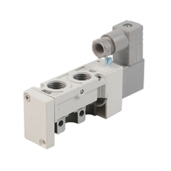
Figure 1: 5/2-way pneumatic solenoid valve
5/2-way and 4/2-way pneumatic solenoid valves direct compressed air to various pneumatic devices, such as pneumatic cylinders. The main difference between these valves is in their number of ports and position states:
- The 5/2-way pneumatic solenoid valve has five ports and two switching positions.
- The 4/2-way pneumatic solenoid valve has four ports and two switching positions.
Both operate similarly to manage pneumatic devices like double-acting pneumatic cylinders. However, they differ in how they handle exhaust air.
- A 5/2-way valve sends air into one cylinder port while exhausting from the other. The fifth port gives more control by allowing separate exhaust paths for each cylinder port.
- A 4/2-way valve also manages input and exhaust air but uses the same exhaust path for both ports. This setup needs equal exhaust flow in both directions.
Table of contents
- Port designations
- Circuit function
- Mono-stable vs bi-stable
- Design
- Applications
- Selection criteria
- FAQs
View our online selection of 5/2-way pneumatic solenoid valves!
Port designations
Manufacturers may use different port labeling systems, but the concepts are the same. Figure 2 shows two common standards: numbers (ISO 11727) and letters.
- 5/2-way numbers (A): Supply air port (1), outlet ports (2, 4), and exhaust ports (3, 5)
- 5/2-way letters (B): Supply air port (P), outlet ports (A, B), and exhaust ports (EA, EB).
- 4/2-way numbers (C): Supply air port (1), outlet ports (2, 4), and exhaust port (3).
- 4/2-way letters (D): Supply air port (P), outlet ports (A, B), and exhaust port (R).
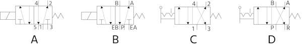
Figure 2: Pneumatic solenoid valve ports are typically designated with either numbers or letters.
Circuit function
The valve's circuit function describes which ports are connected in each of the valve's states. When energized, the valve moves from one state to another, and in the case of mono-stable valves (see below), a spring returns the valve to its original position when de-energized.
- 5/2 State 1: The supply pressure port (1, P) connects to port 2 (A). Port 4 (B) exhausts through port 5 (EB).
- 5/2 State 2: The supply pressure port (1, P) connects to port 4 (B). Port 2 (A) exhausts through port 3 (EA).
- 4/2 State 1: The supply pressure port (1, P) connects to port 2 (A). Port 4 (B) exhausts through port 3 (R).
- 4/2 State 2: The supply pressure port (1, P) connects to port 4 (B). Port 2 (A) exhausts through port 3 (R).
Mono-stable vs bi-stable
Both five and four way air valves can be mono-stable or bi-stable.
- Mono-stable: This valve has one solenoid coil. When the coil is powered, the internal spool moves from its default position. A spring returns the spool to its original position when power is lost. Continuous power is needed to hold the spool in the actuated position. (See Figure 3: A & C)
- Bi-stable: This valve has two solenoid coils. The spool moves to a position when one coil is energized. It stays in that position even after power is removed. To move the spool back, the other coil must be energized. (See Figure 3: B & D)
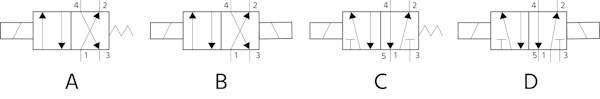
Figure 3: 4/2 valve mono-stable (A), 4/2-way bi-stable (B), 5/2-way mono-stable (C), and 5/2-way bi-stable (D).
Design
5/2 and 4/2-way pneumatic solenoid valves come in many designs. These may vary in size, material, color, connection type, and more. This variety meets the needs of different industries, including medical, food processing, and explosive environments.
Most valves use a central cylinder with a movable spool. The spool has seals along its length. As the spool moves, the seals connect or block port openings to control the air path.
Direct and pilot operated
Pneumatic solenoid valves can be direct or pilot (indirect) operated:
- Direct: The magnetic actuator directly moves the spool.
- Pilot: The valve uses inlet pressure to help move the spool. A small internal pneumatic cylinder actuates the spool. The valve's magnetic actuator controls the filling and emptying of the cylinder.
Manual override
Both 5/2 and 4/2 valves can include a manual override or lock mechanism. The lock is useful during maintenance, keeping the valve in one position until the lock is released. This feature:
- Allows testing the system without powering the valve
- Keeps actuators like cylinders and grippers in place
- Lets the valve be manually switched by pressing the override
Connector types
Pneumatic solenoid valves offer various connector types based on valve needs. Some connectors protect against power surges or include LEDs to show power status. More about connectors is available in the DIN connector overview article.
Applications
4/2 and 5/2-way pneumatic solenoid valves can both operate double acting pneumatic cylinders and pneumatic actuators that require control in both directions. A 5 2 valve, however, with its extra exhaust port, can independently control the exhaust rate in both directions, whereas a 4/2-way valve requires both directions to share the same exhaust rate.
Controlled exhaust in both directions
- High-speed applications: In high-speed applications, such as packaging, sorting systems, or assembly lines, the speed of actuation is crucial. A 5 2 way solenoid valve with separate exhaust paths can allow for quicker air pressure exhaust, resulting in faster actuation times.
- Precision applications: In applications requiring precise control of movement, like in robotics or precision machining, separate exhaust paths can provide better control of the actuation speed in both directions.
- Safety-critical applications: In safety-critical applications where the failure of one part could have serious consequences, separate exhaust paths can provide redundancy. If one exhaust path fails, the other can still function.
Same exhaust in both directions
- Single-acting cylinder applications: In applications using single-acting cylinders where spring return is used, a common exhaust path (four way air valve) is sufficient since the return action is not dependent on the exhaust air.
- Less critical speed applications: In applications where speed of actuation is not critical, a common exhaust path can be used. This might include general purpose pneumatic systems, door openers, or simple mechanical movements.
- Cost-sensitive applications: 4 way 2 position solenoid valves can be less expensive than 5 way solenoid valves. If the application doesn't require high speed or precision, a 4/2 way pneumatic valve might be more cost-effective.
Selection criteria
- Connection size: Connection sizes range from small sizes like 1/8 inch and M3 to larger sizes like 1/2 inch and QS-8, accommodating various piping and tubing systems.
- Connection type: These valves offer diverse connection types, including flange, threaded (NPT, BSPP-G), metric threads, NAMUR, and sub-base.
- Function: The valves can be configured for different functions such as normally closed, bistable, monostable, detent, bistable dominant, and exhausted.
- Voltage: They support a wide range of voltage options, including 12 V DC, 24 V AC/DC, 110 V AC, 115 V AC, 230 V AC, and 22 V DC, catering to different electrical systems and requirements.
- Material: Constructed from materials like aluminum, stainless steel, and various aluminum alloys (some anodized or painted), these valves offer durability and resistance to environmental factors.
-
Seal material:Seal materials such as NBR, FKM, HNBR, thermoplastic polyurethane, and others ensure compatibility with different media and operating conditions, providing reliable sealing performance.
- Note: Read our chemical resistance of materials guide for more information on the body and seal materials.
- Max pressure: The valves can handle maximum pressures ranging from 7 to 12 bar (101.5 to 174 psi), making them suitable for various industrial applications with different pressure requirements.
- Min pressure difference: They operate effectively with minimum pressure differences from -0.95 to 3 bar (-13.78 to 43.51 psi).
- Valve bore: Valve bore sizes range from 1 to 50 mm (0.039 to 1.969 in), providing options for different flow capacities and system requirements.
- Kv value [m³/h]: With Kv values ranging from 0 to 4 m³/h, these valves offer precise flow control for various applications.
- Min temperature: They can operate in temperatures as low as -25 °C (-13 °F), making them suitable for cold environments.
- Max temperature: The maximum operating temperatures range from 40 to 70 °C (104 °F to 158 °F), accommodating a variety of thermal conditions.
- Degree of protection (IP): IP ratings such as IP40, IP65, and IP67 indicate the level of protection against dust and water, ensuring reliability in different environments.
- Nominal power [W]: With nominal power consumption ranging from 0 to 5 watts, these valves are designed for energy-efficient operation.
- Max control pressure: Max control pressure is for pilot-controlled valves with an external pilot supply. The maximum control pressure options of 8 and 10 bar (116.03 to 145.04 psi) allow for precise control in demanding applications.
- Min control pressure: Minimum control pressures from 0.5 to 3 bar (7.25 to 43.51 psi).
- Max flow rate [l/min]: The valves support maximum flow rates from 80 to 4500 l/min, catering to both low and high-flow applications.
- Approval: Approvals such as ATEX Zone 1 and 21, cULus, KC EMC, EU EMC, and RCM compliance mark ensure compliance with safety and regulatory standards.
- Return actuation: Return actuation options include spring return, air spring return, mechanical spring, and pneumatic spring.
FAQs
What is a 5/2 way solenoid valve?
A 5 2 solenoid valve has five ports and two states. It can switch between two different states to control airflow to and exhaust from both air ports of a pneumatic cylinder or actuator.
What is a 4 way solenoid valve?
A four way two position valve has four ports and two positions. Two ports supply air to either side of a double acting solenoid valve and the remaining port handles exhaust from the cylinder.
