


Pneumatic Cylinders - Working Principle and Types
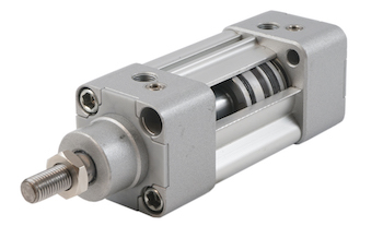
Figure 1: Pneumatic cylinder
A pneumatic cylinder converts compressed air energy into a reciprocating linear motion. They are simple to use and are a cost-efficient solution to move loads linearly, making them commonly used in industrial applications where automation is required, such as in manufacturing, assembly lines, and robotics. This article gives a complete overview of how pneumatic cylinders work, the different types of pneumatic cylinders, their important qualities, and how to select them for an application.
Table of contents
- Pneumatic cylinder parts
- Pneumatic cylinder working principle
- Stroke length, speed, and time
- Calculating force
- Standards
- Rodless cylinders
- Cushioning
- Pneumatic cylinder accessories
- Symbols
- Selection criteria
- Pneumatic cylinder maintenance
- FAQs
View our online selection of pneumatic cylinders


Pneumatic cylinder parts
Figure 2 shows the main components of a double-acting pneumatic cylinder.
- Cap-end port (A): The cap on the backend of the pneumatic cylinder where compressed air can enter or exit.
- Tie rod (B): Tie rods are long rods that hold the pneumatic cylinder together. They run the length of the pneumatic cylinder and connect the cap and rod-end heads together.
- Rod-end port (C): The cap on the rod-end of the pneumatic cylinder where compressed air can enter or exit.
- Piston (D): A disc shaped element that moves inside the cylinder. It moves in response to changes in air pressure and connects to the piston rod.
- Barrel (E): The cylindrical body that contains the piston.
- Piston rod (F): The piston rod connects to the piston and moves with it to create linear motion. The end of the piston rod is typically attached to an attachment or the load.
Learn more about these parts in our pneumatic cylinder parts article.
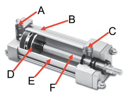
Figure 2: Double-acting pneumatic cylinder parts: cap-end port (A), tie rod (B), rod-end port (C), piston (D), barrel (E), and piston rod (F).
Pneumatic cylinder working principle
The general working principle of a pneumatic cylinder depends on whether the cylinder is single- or double-acting. A short description is below, but see our single acting vs double acting pneumatic cylinder article to learn more.
Single-acting pneumatic cylinder
A single-acting pneumatic cylinder uses compressed air to drive the piston in only one direction. A mechanical spring moves the piston to its original position. Figure 3 shows the two design possibilities. Figure 3 label A shows that the spring is used to extend the piston outward and compressed air retracts the piston inward. Figure 3 label B shows that the spring is used to retract the piston inward and compressed air is used to extend the piston outward. Single-acting cylinders are often used for fail-safe applications that require the piston to be in a certain position upon compressed air loss.
Due to the opposing spring force, single-acting pneumatic cylinders do not provide a consistent output force throughout the piston stroke. Furthermore, the stroke of single-acting cylinders is limited due to the space necessary for the compressed spring.
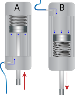
Figure 3: Single-acting pneumatic cylinder working principle. Compressed air moves the piston in one direction, and a spring either extends the piston (A) or retracts it (B).
Double-acting pneumatic cylinder
Double-acting pneumatic cylinders allow for complete control of the piston's movement. Figure 4 shows how the piston and piston rod move when compressed air enters the cap-end and rod-end ports.
- Positive position (A): The rod is extended from the body.
- Negative position (B): The rod is retracted into the body.
Compressed air enters the cap-end port and pushes the piston forward, extending the piston rod (Figure 3 labeled A). Air exits the rod-end exhaust port. To retract the piston rod, compressed air enters the rod-end port, forcing air out of the cap-end exhaust port and forcing the piston to retract (Figure 3 labeled B).
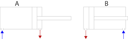
Figure 4: The working principle of a double-acting pneumatic cylinder. The blue arrows represent the ports receiving the compressed air, pushing the piston away from the port: positive position (A) and negative position (B).
Double-acting pneumatic cylinders allow for complete control, extended piston stroke length, and a constant output force through the entire stroke. Since they use compressed air in both directions, they use more energy. They can also operate at higher cycling rates. However, a double-acting cylinder is not applicable for systems that require the cylinder to be in a certain position upon failure and the loss of compressed air.
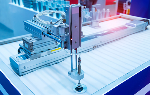
Figure 5: A vacuum pick and place application using a pneumatic cylinder to move the position of the suction cup.
Stroke length, speed, and time
A pneumatic cylinder's stroke length, full stroke time, and speed significantly impact the cylinder's performance and efficiency in a system.
- Stroke length: A pneumatic cylinder's stroke length is the maximum distance that a pneumatic cylinder can move its load.
- Full stroke time: The time necessary for the cylinder's rod to move from fully extended to fully retracted or vice versa.
- Speed: The piston rod's speed is determined by dividing the stroke length by the stroke time.
Calculating force
To select a pneumatic cylinder, it's important to first understand how much force is necessary to move the load at the desired speed. The cylinder chosen to move the load should have a force rating slightly higher than the force necessary to move the load. Learn how to do these calculations by reading our pneumatic cylinder force calculator.
Standards
Pneumatic cylinder designs typically adhere to ISO standards, allowing them to be interchangeable with products of different manufacturers. Therefore, the mounting dimensions, cylinder bore, stroke, piston rod characteristics, and air ports depend on the type/standard and use.
Round ISO 6432 (8-25 mm)
ISO 6432 is a metric ISO standard applicable to single-rod pneumatic cylinders with bores from 8 mm to 25 mm and a maximum working pressure of up to 10 bar (1000 kPa). They are commonly referred to as mini air cylinders or round cylinders. This pneumatic cylinder standard does not have manual damping adjustment. ISO 6432 cylinders are suitable for automation systems in diagnostic instrumentation, bottling, automotive, commercial kitchen, and laundry equipment.
Note: Round cylinders with bore sizes larger than 25 mm are available. However, because of their size, they do not fully adhere to the ISO 6432 standard.
Profile ISO 15552 (32-320 mm)
ISO 15552 establishes standards for single or double-rod pneumatic cylinders with a maximum working pressure of up to 10 bar (1000 kPa) and bore sizes from 32 mm to 320 mm. This standard applies to cylinders with detachable mountings. The ISO 15552 pneumatic cylinder series has adjustable cushioning, which helps to achieve perfect dampening. Therefore, ISO 15552 cylinders are suitable for efficiently moving large loads. They are generally used in automation systems in machine and systems construction and the food and beverage industry. ISO 15552 has replaced the older standards of ISO 6431 and VDMA 24562.
Compact ISO 21287 (20-100 mm)
ISO 21287 applies to single-rod compact pneumatic cylinders with a maximum working pressure of up to 10 bar (1000 kPa) and bore sizes from 20 mm to 100 mm. This pneumatic cylinder series is not equipped with adjustable cushioning. However, there are rubber bumpers at both ends for cushioning. The ISO 21287 pneumatic cylinder series are compact and lightweight, thus desirable for applications with space limitations.
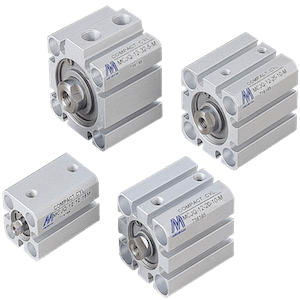
Figure 6: ISO 21287 pneumatic cylinders
Rodless cylinders
A rodless cylinder moves the load alongside the piston rather than pushing or pulling the load with the piston. These cylinders are more compact for the same stroke length. They have the same force in both directions and no piston rod buckling. Rodless cylinders are commonly used for material handling, loading, lifting, and web cutting. Read our rodless cylinder technical article for more information.
Cushioning
The movement of the piston in a pneumatic cylinder can be very fast as the compressed air enters the cylinder. This fast movement can create a hard shock when the piston hits the head or end cap. This shock imposes stress on the air cylinder components, makes a noise, and transmits vibration to the machine structure. To prevent this, cushioning at the caps is used to decelerate the piston. Cushioning can also prevent the piston from rebounding (bouncing) off the end position. Most pneumatic cylinders have end-of-stroke cushioning in one of the following ways:
- Flexible shock absorbers: These shock absorbers are best suited for slow operating speeds, low loads, and shorter strokes. Their material is often elastomers that come in the form of a ring.
- Adjustable pneumatic cushioning: This style of cushioning is for larger pneumatic cylinders with higher piston speeds or stronger forces. A certain volume of air, which is trapped at the piston's end position, absorbs the shock.
- Self-adjusting pneumatic cushioning: This style of cushioning also uses trapped air to absorb shock, but it can self-adjust to varying forces. It does not require manual adjustment. Self-adjusting pneumatic cushioning is best for applications with varying forces.
Pneumatic cylinder accessories
Piston position feedback
Pneumatic cylinder sensors provide piston position feedback to a control system in automated machinery and equipment. It is typically standard that the piston has a magnet inside the cylinder's body. Then, a sensor can be mounted onto the pneumatic cylinder body, as Figure 6 shows, to provide the position of the piston. Depending on where the sensor is mounted, it can detect extension, retraction, or individual positions along the cylinder body. Multiple sensors can be mounted to the body of the cylinder if multiple-position feedback is needed.
Reed sensors are the most common type of sensor as they have a long life cycle (over 10 million) and are typically not the first point of failure for high shock or vibration applications. Read our pneumatic cylinder sensor article to learn more about how they work.
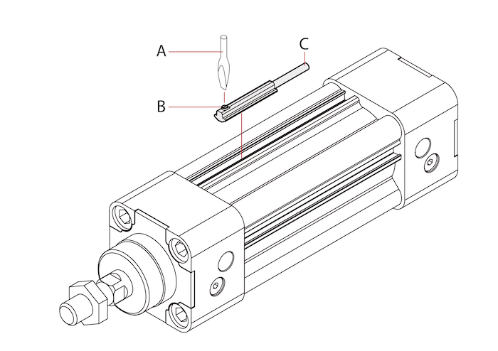
Figure 7: Use a screwdriver (A) and a set screw (B) to mount a position sensor (C) to the pneumatic cylinder's body.
Pneumatic grippers
A pneumatic gripper is a pick-and-place device that uses compressed air to operate gripper jaws, also called fingers. They typically have two or three fingers and have an internal pneumatic cylinder to operate and control them. They are mostly used in automated manufacturing processes to grip a workpiece. Read our pneumatic gripper article to learn more about how they work.
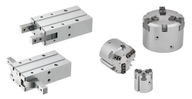
Figure 8: Pneumatic grippers
Mounting accessories
Mounting accessories are used to mount the pneumatic cylinder or for coupling the piston rod to a load. They are typically designed based on the ISO standard of the pneumatic cylinder. Mounting accessories will affect system performance, reliability, and overall design. Flanges, food mounted, pivots, angle brackets, and spherical eye are just some of the different mounting accessories. Read our articles on rod-end and mounting accessories.
Symbols
ISO has developed well-defined symbols for pneumatic cylinders to distinguish their function in schematics. These symbols are independent of pneumatic cylinder ISO standards, diameter, or stroke.
| Double-acting cylinder | 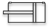 |
| Double-acting cylinder with magnetic piston |  |
| Double-acting cylinder with adjustable cushioning | 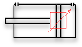 |
| Double-acting cylinder with adjustable cushioning and magnetic piston | 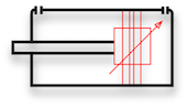 |
| Double-acting cylinder with through piston rod, adjustable cushioning and magnetic piston | 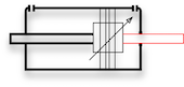 |
| Single-acting cylinder (minus) | 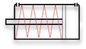 |
| Single-acting cylinder (plus) | 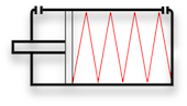 |
Selection criteria
Selecting a pneumatic cylinder depends on the following factors. Read our article on selecting a pneumatic cylinder to learn more about each pneumatic cylinder selection criteria:
- Force
- Stroke length
- Mounting style
- Position feedback
- Cushioning
- Cylinder diameter
- Operating pressure
- Connection size
- ISO standards
Pneumatic cylinder maintenance
Pneumatic cylinders are reliable but can accumulate wear and damage over time. This leads to poorer performance and, at worst, failure. Proper maintenance includes inspection and repair, which can help prevent issues with the cylinder, extending its life.
FAQs
What does a pneumatic cylinder do?
A pneumatic cylinder is a mechanical device that converts compressed air energy into a reciprocating linear motion.
Can pneumatic cylinders stop mid-stroke?
Double-acting cylinders are capable of stopping mid-stroke. For high-accuracy applications, special locking cylinders and position feedback should be used.
How do pneumatic cylinders work?
A double-acting pneumatic cylinder uses compressed air to move a piston in and out, while a single-acting pneumatic cylinder uses compressed air for one-way movement and a return spring for the other.
What does stroke mean for pneumatic cylinders?
The stroke is the total distance that the piston rod is capable of moving in one direction.


