Vacuum Pick And Place System
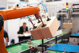
Figure 1: Vacuum pick and place application
Vacuum pick and place applications utilize vacuum tools for automated lift and release of workpieces. These pick and place tools are widely seen in modern manufacturing applications for automatic material handling. Vacuum systems make such applications efficient and cost-effective and this article covers the various components that go into these systems. Vacuum systems are seen in the following types of pick and place applications:
- Automatic assembly of parts in electronic device manufacturing
- Lifting and stacking one or multiple boxes in warehouses
- Picking up the defective items from the conveyor belt
- Packaging of food products in food processing facilities
- Lifting glass panes or floor tiles
- Lifting sheet metals, injection molded parts in automotive manufacturing
Vacuum pick and place system
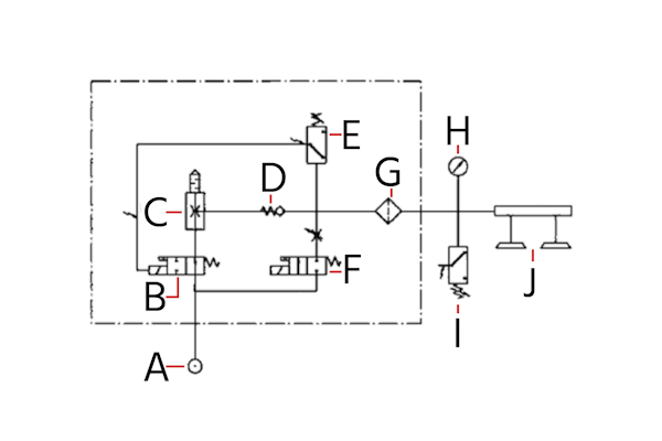
Figure 2: Vacuum pick and place application components: compressed air entry point (A), control valve (B), vacuum generator (C), non-return valve (D), vacuum switch (E), compressed air blow-off valve (F), vacuum filter (G), vacuum pressure gauge (H), external vacuum switch (I), and vacuum suction cups (J)
Figure 2 illustrates the components of a vacuum pick and place system.
Compressed air entry point (A)
Compressed air enters the system, serving as the power source for generating vacuum.
Control valve (B)
Valves help in monitoring the vacuum level and ensuring the proper flow of compressed air into the system. The compressed air control valve directs the flow of compressed air into the system, preventing any backflow.
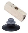
Vacuum generator (C)
Vacuum generators in pick and place systems utilize compressed air to create a vacuum, enabling suction cups to securely attach to objects. These generators can be either single or multi-staged, with multi-stage generators offering higher suction rates for efficient operation. For optimal performance in pick and place applications, it's crucial to determine the required suction force and response time. Typically, ensuring a strong grip involves selecting a generator that can maintain the necessary vacuum level, considering factors like the vacuum line length which can affect response time. By understanding these specifics, one can choose the most appropriate vacuum generator, ensuring the system efficiently handles the desired objects with precision and speed.
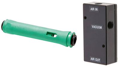
Figure 3: Vacuum generators
Non-return valve (D)
The non-return valve (check valve) prevents the vacuum from losing pressure by blocking the reverse flow of air, ensuring the vacuum remains stable during operation. It is typically installed after the vacuum generator.
External vacuum switch (E)
An additional control mechanism that can be used to activate or deactivate the vacuum externally, providing flexibility in how the system is operated. This allows for precise control over the pick and place process, enabling the system to adapt to different tasks or materials without the need for manual adjustment.
Compressed air control valve (F)
In a vacuum pick and place system, the operation begins with the creation of a vacuum to adhere the suction cups to the workpiece. This is achieved by using a pneumatic solenoid valve to control the main air supply or actuators in the compressed air system. As these valves open, air is evacuated from the space between the valve and the suction cup, creating the necessary vacuum for the suction cup to securely attach to the object. Once the object needs to be released, the compressed air control valve comes into play. It releases compressed air to quickly break the vacuum seal formed between the suction cup and the object. This efficient mechanism allows the suction cups to release the picked objects without delay, ensuring a smooth operation in the pick and place process.
Direct-acting (process) valves are typically used as vacuum valves as they do not require a minimum differential pressure. Externally piloted pneumatic valves can also be used. The flow direction of the air should be carefully considered during the installation of these vacuum valves. As the valve has one specified flow direction, the compressed air should be allowed to pass from high pressure to low-pressure port. This means the outlet port of the valve should be connected at the vacuum side of the application.
To learn more about the use of valves in vacuum systems read our article on the use of solenoid valves in vacuum applications and ball valves in vacuum systems.
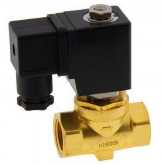
Figure 4: 2-way semi-direct vacuum solenoid valve
Vacuum filter (G)
The vacuum filter cleans the air drawn into the system, protecting the vacuum generator from dust and debris that could impair its function.
Vacuum pressure gauge (H)
A vacuum pressure gauge is used in pick and place applications to read the pressure readings below atmospheric levels. These gauges are installed near the inlet of the suction cup and/or near the outlet of the compressed air source. The negative reading (with respect to the atmospheric pressure) in the pressure gauge indicates the vacuum pressure. Generally, a bourdon tube pressure gauge is used for moderate vacuum pressure reading. For high vacuum reading, a specially designed highly sensitive pressure gauge is used. Temperature, pressure, and accuracy required for the application are important factors in selecting a pressure gauge. For a vacuum gauge, ± 0.025 bar deviation is preferred.
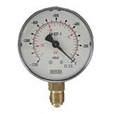
Figure 5: Vacuum pressure gauge
Vacuum suction cups (I)
These are the end-effectors that physically contact and hold onto the objects being moved. They adhere to surfaces using the vacuum pressure. A vacuum suction cup is a component that comes in direct contact with the workpiece in a pick and place application. The vacuum generator removes the air between the surface of the suction cup and the workpiece creating a vacuum. The atmospheric pressure becomes more than the pressure between the cup and the workpiece causing the vacuum suction cup to attach against the workpiece. In general, the force exerted by the vacuum suction is calculated as:
F = PA
Where,
- F = holding force,
- ∆P = difference between atmospheric pressure and pressure inside the suction cup
- A = effective suction area
Load orientation and the type of suction cup used to hold the workpiece also affect the force. Commonly used vacuum suction cup types include flat vacuum, oval vacuum, and bellow vacuum suction cups. The required safety factor and coefficient of friction are also required to be known when calculating the needed lifting force.
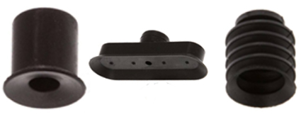
Figure 6: Vacuum suction cups
Internal vacuum switch (J)
Similar to the external vacuum switch, an internal vacuum switch controls the vacuum from within the system, offering an integrated method for managing the vacuum's operation.
Additional components
Hoses
Pneumatic hoses are required to convey compressed air for the pick and place application. These hoses must be able to withstand high pressure to operate with compressed air without leakage. It is advisable not to use thin tubing as it can collapse under a vacuum even on moderate heat. The hoses must be sized to meet the flow volume requirement and the size of the suction cups.
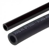
Figure 7: Hoses for compressed air
Fittings
Vacuum tools are generally accompanied by fixed or detachable fittings to connect them to a compressed airline. Properly installed fittings prevent leakage and ensure a proper flow path for the compressed air. These fittings should be able to handle light workpieces without causing any bending stress in the suction cup. Push-in pneumatic fittings and other pneumatic couplings (manifolds, safety couplings, etc.) are often used. Consider the following parameters while selecting a fitting:
- Select fittings based on suction cup size and type
- Consider the material being handled (porous vs. non-porous)
- Ensure proper sizing for the bore size of the fitting and the vacuum line
- Account for the application's required temperature and pressure
- Preferred materials for fittings include aluminum and brass
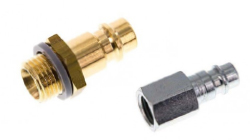
Figure 8: Fittings for vacuum application