


Pneumatic Cylinder Parts
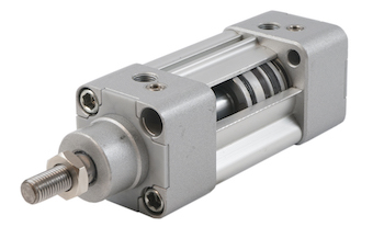
Figure 1: Pneumatic cylinder
Pneumatic cylinders use compressed air to create linear motion in various industrial and commercial applications. These cylinders contain several parts which vary depending on the type and design of the cylinder. This article explores the different parts of a pneumatic cylinder and their functions.
Table of contents
View our online selection of pneumatic cylinders


What is a pneumatic cylinder?
Pneumatic cylinders convert compressed air energy into reciprocating linear motion. They are classified in multiple ways:
- Design: Pneumatic cylinders with piston rods, diaphragm, rotary, and rodless cylinders.
- Movement: Linear and rotary cylinders.
- Function:Single-acting vs double-acting pneumatic cylinders.
- Cushioning: Pneumatic cylinders with adjustable or flexible cushioning.
The configuration and components of a pneumatic cylinder depend upon its classification. The following section explains the primary constituents of a dual-acting pneumatic cylinder while also making notable references to alternative varieties and their deviations relative to the dual-acting classification.
Like any mechanical device, pneumatic cylinders require maintenance, and sometimes certain parts need to be replaced to ensure optimal performance. Read our pneumatics glossary for more information on pneumatic system components.
Pneumatic cylinder parts
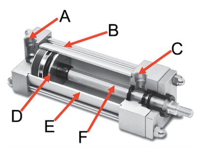
Figure 2: Pneumatic cylinder parts: cap-end port (A), tie rod (B), rod-end port (C), piston (D), barrel (E), and piston rod (F).
Barrel
The barrel (Figure 2 labeled E), the main body of the cylinder, houses the piston and provides mechanical support for the cylinder. It is typically cylindrical and can be made of aluminum, stainless steel, or plastic.
End cap
- The barrel is sealed by two end caps, the front-end cap (head) and the rear-end cap.
- The front-end cap sits next to where the piston rod protrudes, while the rear-end cap sits opposite.
- One (in the case of a single-acting cylinder) or both caps (in a double-acting cylinder) feature ports that allow pressurized air into the bore (Figure 2 labeled A and C).
Piston
The piston (Figure 2 labeled D) is a disc that moves within the pneumatic cylinder, thus dividing the chamber. It moves back and forth along a straight line. When compressed air enters the read-end cap, it pushes the piston to extend the rod. This causes the piston to shift from the rear-end cap and extend the rod. This movement is called a positive (or plus) movement, and retraction of the piston is called negative (or minus) movement (Figure 3).
- Single-acting cylinder: A spring around the piston rod in single-acting pneumatic cylinders assists with retracting the piston and rod assembly.
- Double-acting cylinder: Compressed air moves the piston in both directions.
- Rodless pneumatic cylinder: In a rodless cylinder, the piston is replaced with a carriage or shuttle that slides back and forth inside the cylinder wall. The carriage is connected to the load to be moved, and no piston rod extends outside the cylinder. Instead, the cylinder has a hollow piston that provides the necessary support for the carriage.
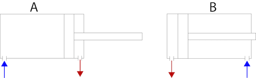
Figure 3: Double-acting cylinder working principle with air going in (blue arrow) and air coming out (gray arrow). Positive movement (A) extends the rod and negative movement (B) retracts the rod.
Piston rod
The piston rod (Figure 2 labeled F) connects to and is driven by the piston. It also attaches to the machine element or object to be pulled or pushed. The distance the piston and rod travel is known as the stroke length.
Piston cushioning
At times, different components in production facilities must move fast. When using pneumatic cylinders, this results in the release of high energy when the fast-moving cylinder comes to a stop. It is essential to dampen the end position appropriately in a controlled manner.
Piston cushioning slows down the rod and piston assembly before reaching the end cap. This absorbs the kinetic energy as efficiently as possible, minimizing wear, tear, and shock. This also reduces noise, impact, and vibration toward the end of each stroke and allows the piston to move at higher speeds.
There are mainly three methods to dampen pneumatic cylinders.
- Elastic damping: In elastic damping, the piston rod collides at a certain speed with an elastic material that deforms its shape. The material returns to its original shape after the cylinder rod has retracted, preparing it for the next impact.
- Pneumatic damping: Compressed air slows down the pneumatic cylinder in pneumatic damping. This is achieved by a fixed amount of back pressure, which depends on the cylinder's speed at the damping time.
- Hydraulic damping: In hydraulic damping, viscous fluids like oil slow down the cylinders.
Static seal
The piston's static seal ensures a tight seal between the rod and the piston, preventing air from escaping to the other side of the chamber.
Piston guide rings
Piston guide rings prevent any metal-to-metal contact between the cylindrical chamber and the piston during sliding and absorb any radial forces that may act on the cylinder.
Sensors
Pneumatic cylinder sensors detect the position of the piston within the cylinder, which is vital for positioning applications. Hall-effect sensors and reed switches are commonly used in these sensors.
Tie rods
Tie rods (Figure 2 labeled B) secure the end caps in place. They are usually threaded steel rods. These rods run through the entire cylinder length. Pneumatic cylinders typically have approximately four to twenty tie rods depending on the size and force created. Tie rods protect the pneumatic cylinder from shocks and other potential impacts.
FAQ
What are the main parts of pneumatic cylinders?
The main parts of pneumatic cylinders are the barrel, piston, and piston rod. Seals, cushioning systems, sensors, guide rings, and tie rods enhance the performance and prolongs the service life of pneumatic cylinders.


