


Pneumatic Cylinder Full Stroke Time & Speed
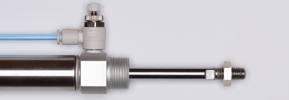
Figure 1: Pneumatic cylinder stroke
Pneumatic cylinders are widely used in industrial and automation applications to convert compressed air into linear motion. Speed and full stroke time are critical factors in the performance of a pneumatic cylinder; they significantly affect its efficiency and productivity. Various factors, including the size and type of cylinder, air pressure, and load influence the speed of a pneumatic cylinder. This article covers how to select a pneumatic cylinder based on its full stroke time and the different factors that impact its speed and provides insights on optimizing the cylinder's performance. Read our pneumatic cylinder overview article for more details on the design and working of pneumatic cylinders.
Table of contents
- Full stroke time
- Pneumatic cylinder speed
- Speed vs bore size in a pneumatic cylinder
- Ideal velocity profile
- Pneumatic cylinder stroke vs time
- How to control pneumatic cylinder speed
- Pneumatic cylinders with cushioning
- Example
- FAQs
View our online selection of pneumatic cylinders


Full stroke time
The full stroke time of a pneumatic cylinder is the amount of time it takes for the cylinder to move from its fully extended position to its fully retracted position or vice versa. The estimation of full stroke time takes into account factors such as the cylinder's bore size, stroke length, air pressure, and load; it is a widely used parameter for selecting a pneumatic cylinder.
Calculation and speed adjustment
A user can estimate the velocity of a pneumatic cylinder by dividing the piston rod's stroke length by its cycle time. This calculation provides an idea of the rate at which the cylinder's piston rod will act on an object during each cycle. For instance, if a pneumatic cylinder with a stroke length of 100 mm is used to actuate a load every 1 second, the cylinder will generate a stroke-end velocity of 100 mm/s.
To reduce the stroke time to move an object, the user can increase the velocity of the pneumatic cylinder using the techniques discussed later in this article. If the velocity has hit its maximum, and the stroke time cannot be reduced further, it may be a cue to change the cylinder.
Example
Consider moving an object 300 mm within 2 seconds for both strokes of the pneumatic cylinder. Calculate the necessary speed required by the cylinder.
Speed = Distance / Time
Speed = 300 mm / 2 s = 150 mm / s
Therefore, choose a pneumatic cylinder that operates at a velocity of 150 mm/s.
Pneumatic cylinder speed
Stroke-end velocity is the velocity of the piston when it reaches the end of its stroke or an arbitrary position. This velocity is influenced by several factors, including the load being moved, the air pressure applied, the length and diameter of the tubing connecting the cylinder and control valve, and the flow rate of the control valve. Generally, a standard cylinder can achieve an average speed of 0.1 to 1.5 meters per second.
Pneumatic cylinder speed calculation involves the following general formula:
- V: Pneumatic cylinder velocity (m/s)
- Q: Flow rate (m3/s)
- A: Piston area (m2)
Use the following equation if the flow rate is given in CFM (cubic feet/min) and the piston area is given in square inches. The constant 28.8 takes into account the conversion factors from feet to inches and minutes to seconds. The resultant velocity is obtained in inches/second.
- V: Pneumatic cylinder velocity (in/s)
- Q: Volumetric flow rate (CFM, cubic feet/min)
- A: Piston area (square inches)
The effective piston area can be calculated using the formula:
- d: Piston diameter (in)
Example
Calculate the velocity of a pneumatic cylinder with a piston area of 0.3 square meters and a flow rate of 100 cubic meters/s.
Q = 100 cubic meters/s
A = 0.3 square meters
V = 100/0.3 = 333.3 m/s
Speed vs bore size in a pneumatic cylinder
For two pneumatic cylinders of the same length, the one with a smaller bore diameter will operate faster than one with a larger bore diameter. This is because smaller bore cylinders require less compressed air and can be filled more quickly by the air pump. Additionally, the mechanical resistance of the cylinder also affects its speed. Choosing a cylinder that can handle 50% more force than required to achieve high speeds is recommended. Figure 2 shows the pneumatic cylinder speed chart comparing the cylinder speed with the bore size. The chart estimates under optimal conditions, assuming constant air supply, no load, disregarding acceleration, and actual working speed may be slower.
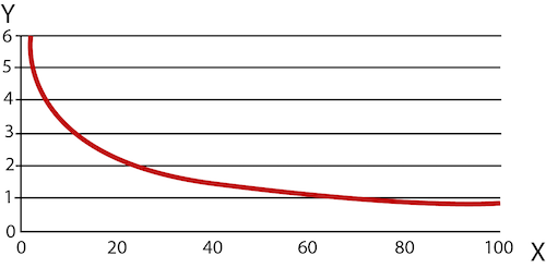
Figure 2: Pneumatic cylinder speed chart (speed vs bore size). The X-axis and the Y-axis show the cylinder speed and bore size, respectively.
Ideal velocity profile
To maximize the machine output, it is necessary to operate cylinders at high speed without causing malfunctions. This entails operating the cylinder at its maximum velocity for as much of its stroke as possible (Figure 3 labeled A), with constant acceleration and deceleration at each end of the stroke (Figure 3 labeled B). The deceleration phase ensures that the cylinder stops at the end cap without any impact loading.
Impact loading in pneumatic cylinders occurs when the cylinder and the moving load come into contact at high speeds, resulting in a sudden force being applied to the cylinder. This can happen when the cylinder reaches the end of its stroke or when a sudden stop or reversal occurs, causing damage to the cylinder and other components in the system, such as valves and fittings. The constant acceleration should result in forces that are safe for the cylinder's working load according to Newton's law (F = ma).
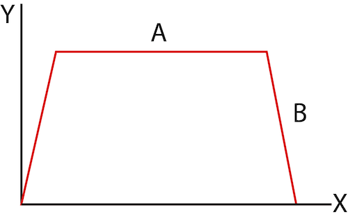
Figure 3: Ideal velocity profile of a pneumatic cylinder showing the constant maximum velocity (A) and linear acceleration at maximum force (B). The X-axis and Y-axis show the piston position and velocity, respectively.
Pneumatic cylinder stroke vs time
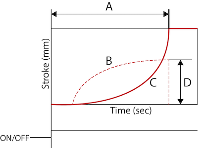
Figure 4: Top: Pneumatic cylinder stroke vs time: full stroke time (A), velocity (B), stroke length (C), and stroke end velocity (D). Bottom: The opening of the solenoid valve to supply air into the pneumatic cylinder.
Figure 4 shows the relationship between pneumatic cylinder stroke length and time.
- A: The time it takes for the piston rod to complete a full stroke
- B: Pneumatic cylinder's velocity plot
- C: Pneumatic cylinder's stroke length plot
- D: The velocity at the stroke end
How to control pneumatic cylinder speed
Controlling the speed of a pneumatic cylinder is essential to ensure it operates safely and efficiently. Several components can be used to control the pneumatic cylinder response time. These components slow the airflow in one direction, so if only one is used on a double-acting pneumatic cylinder, the cylinder will be fast in one direction but slow in the other. Using flow control on both cylinder ports will slow it in both directions. Experimentation is necessary with the real application to determine the time required, as it varies due to resistance and friction.
- Adjusting the air pressure: The speed of a pneumatic cylinder is directly proportional to the air supply pressure. To reduce the speed, lower the air supply pressure and vice versa.
- Adding a flow control valve: Installing a flow control valve in the pneumatic cylinder's air supply line can regulate the flow of air and hence the speed of the cylinder. The valve can be adjusted to allow more or less airflow.
- Implement a restrictor: Pneumatic cylinders are commonly equipped with a throttle valve or restrictor to control the piston actuation and/or retraction speed. For example, to slow down a pneumatic cylinder, the user can close the valve output to restrict the airflow out of the cylinder. Similarly, open the valve to speed up the cylinder.
- Employ a pressure regulator: A pressure regulator installed in the air supply line regulates the air pressure and hence the speed of the cylinder. Set the regulator to maintain a specific pressure, which controls the speed of the cylinder.
- Utilize electronic controls: Electronic controls, such as an electronic speed controller, can be used to control the speed of a pneumatic cylinder. The controller can be programmed to adjust the air supply pressure, flow rate, or restrictor setting to control the speed of the cylinder.
There are a few issues with using additional components with pneumatic cylinders to control their speed manually.
- Each cylinder typically requires a few minutes of adjustment during installation and setup. However, if a machine has many cylinders, the time spent on adjusting each can accumulate significantly.
- Adjustable valves can be prone to human error, potentially leading to machine overload and unplanned maintenance.
- The adjustment process must be repeated every time the operating conditions change, which can be laborious and error-prone. If the conditions are constantly changing, it may be impossible to maintain an optimum speed for the cylinder.
In general, the ability of a pneumatic cylinder to consistently maintain its position, speed, and force can be affected by various maintenance factors such as worn seals, leaks, pressure drops, and spikes in the compressed air system. These factors can often make it challenging to achieve reliable and consistent performance.
Pneumatic cylinders with cushioning
Cushioning works by reducing the speed of the piston as it approaches the end of its stroke. Pneumatic cylinders can now be equipped with an innovative 'auto-cushioning' system that can adjust to changing conditions automatically, eliminating the need for manual adjustments. Read our article on pneumatic cylinder cushioning for more information on the working and types of cushioning in pneumatic cylinders.
Example
Consider moving an object 500 mm by a pneumatic cylinder. The user wants to move the object over the distance in 1 second during the extended stroke and in 5 seconds during the return stroke.
For the extended stroke, the object needs to move 500 mm in 1 second, so the average speed required is:
500 mm / 1 s = 500 mm/s
For the return stroke, the object needs to move 500 mm in 5 seconds, so the average speed required is:
500 mm / 5 s = 100 mm/s
To accommodate these different speed requirements, choose a pneumatic cylinder that can operate within a speed range of at least 100 mm/s to 500 mm/s.
Since both the extending and retracting need to be controlled, a double-acting pneumatic cylinder should be used. This cylinder has two ports, one for extending and one for retracting. By connecting both ports to the same pressure source, the cylinder will operate at the same pressure in both directions.
To control the speed of the cylinder during the return stroke, use a flow control valve to regulate the airflow into and out of the cylinder; this allows the user to adjust the speed of the piston. By adjusting the flow control valve, you can ensure that the cylinder operates within the required speed range for each stroke. Another option is to throttle the valve on the output of the cylinder.
Read our ISO 15552, ISO 6432, and ISO 21287 articles for more information on the pneumatic cylinder design features for various ISO standards.
FAQs
How to calculate pneumatic cylinder speed?
The velocity of the pneumatic cylinder is given by V = 28.8×Q/A, where V is the pneumatic cylinder velocity (in/s), Q is the volumetric flow rate (CFM), and A is the piston area (square inches).
Is the speed of a double-acting pneumatic cylinder the same as a single-acting type?
Compared to single-acting cylinders, double-acting cylinders provide greater speed and force output in terms of fluid power.


