Check Valve Flow Explained: Effects on Water Pressure in Pipes

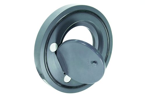
Figure 1: Wafer swing check valve
Effective check valve flow management is crucial for preventing reverse flow, reducing energy consumption, and maintaining consistent pressure in diverse settings such as HVAC systems, fire protection networks, and oil pipelines. Check valves achieve this by using various components like hinges, pistons, screens, flaps, and balls, each allowing fluid to move in one direction while preventing backflow.
The mechanism of action, whether it involves a spring-assisted flap, a gravity-based swing, or a ball, plays a significant role in how the valve interacts with fluid flow. This article examines how different valve designs and installations impact water pressure and flow, exploring the relationship between flow characteristics and pressure drop.
Table of contents
- Key parameters affecting check valve performance
- Pressure considerations in different check valve types
- Check valve pressure drop chart
- FAQs
View our online selection of check valves!
Key parameters affecting check valve performance
Water flow and pressure dynamics
Water pressure is the force exerted to move water through a pipeline, generated either naturally by gravity or artificially by pumps. Water flow refers to the volume of water passing through a pipe at any given time. The relationship between flow and pressure is influenced by several factors, like the pipe diameter. A wider pipe reduces resistance and allows for greater flow capacity at the same pressure, while higher flow rates typically require more pressure if the pipe diameter does not change.
Cracking pressure
The cracking pressure of a check valve is the specific upstream pressure at which a check valve opens, allowing fluid to pass through. It is influenced by the spring tension in spring-loaded valves, which determines the force required to open the valve, and the weight of the flap in swing type valves, which affects the opening pressure. For swing check valves, the cracking pressure is primarily determined by the weight of the flap (disc) and its angle of installation. An adjustable cracking pressure check valve lets users set the pressure at which the valve opens. It typically uses a mechanism like a spring or counterweight to customize it for different systems.
Pressure drop
The check valve pressure drop is affected by:
- Fluid's specific gravity: Heavier fluids have a higher specific gravity, which increases the pressure drop across a check valve due to the greater force required to move the fluid.
- Flow rate: An increased flow rate results in a higher pressure drop because the fluid exerts more force against the valve, requiring more energy to maintain flow.
- Flow coefficient (Cv): A larger flow coefficient (Cv) indicates that the valve allows more fluid to pass through with less resistance, resulting in a lower pressure drop.
Swing check valves generally have a lower pressure drop compared to other types of check valves, such as lift check valves or piston check valves. This is because the design of a swing check valve allows for a more streamlined flow path. In a swing check valve, the disc swings away from the valve seat to allow flow, which creates a relatively unobstructed path for the fluid. This design minimizes turbulence and resistance, resulting in a lower pressure drop.
Pressure considerations in different check valve types
Swing check valves
Swing check valves are primarily designed for horizontal installations. These valves excel in low-pressure situations due to their minimal force requirement for opening, characterized by a low cracking pressure.
-
Vertical installations:
- Upward flow: When installed vertically with upward flow, the disc can slam shut when the flow stops, causing water hammer, which can damage the system.
- Downward flow: In vertical installations with downward flow, gravity keeps the disc open, preventing the valve from closing and stopping backflow, thus failing its primary function.
- Horizontal installations: In horizontal installations, the gravitational force acts perpendicular to the flow direction. The valve relies primarily on the weight of the disc to close, and the required pressure to open the valve is generally lower compared to vertical flow-up installations. This orientation is often preferred for applications where consistent flow is needed without significant pressure drops. In this orientation, gravity does not assist in closing the valve, so the disc relies solely on flow reversal to close. This can lead to more pronounced slamming if the flow reverses quickly.
Read our check valve installation guide article for more details on check valve’s installation position and process.
Spring-loaded check valves
Spring check valves, also known as "silent check valves," use a spring mechanism to assist in the closure of the valve disc. This design allows for a more controlled and gradual closure, minimizing pressure surges and noise associated with water hammer that can occur with swing check valves.
- The spring mechanism results in a higher cracking pressure compared to swing check valves, providing superior backflow resistance. This feature is particularly beneficial in systems with fluctuating pressure conditions or those prone to water hammer effects.
- These valves can be effectively installed horizontally, vertically, or at any inclined angle. This makes them suitable for a wide range of system configurations.
Read our swing vs spring check valve article for more information on how these two types of valves differ in design, operation, and suitability for various applications.
Ball and Y-check valves
- Ball check Valves:Ball check valves use a spherical ball to prevent backflow. While they are simple and reliable, they can create more turbulence and resistance in the flow path, leading to a higher pressure drop compared to other designs.
- Y-type check Valves: The Y-shaped body design of these valves provides a more streamlined flow path, reducing turbulence and pressure drop. This design allows for improved flow characteristics over ball check valves. Additionally, Y-check valves typically have lower shutoff characteristics, meaning they can close more gently, reducing the risk of water hammer.
Check valve pressure drop chart

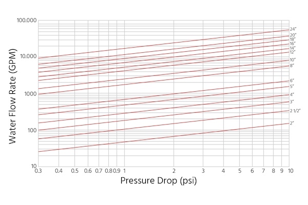
Figure 2: Check valve pressure drop chart example
Note: Pressure drop charts offer useful initial guidance for valve selection, but they assume ideal conditions. Real-world factors like fluid properties, valve construction, and system dynamics can impact performance. For critical applications, consult the manufacturer for precise calculations tailored to specific conditions.
A pressure drop chart for a check valve is a graphical representation specifically designed for each check valve type that illustrates how pressure changes in a fluid system as it passes through the valve. It displays this information for various flow rates and valve sizes. The chart in Figure 2 shows the relationship between flow rate and pressure drop for various sizes of the particular check valve.
- Size-performance correlation: Larger valve sizes allow for significantly higher flow rates at the same pressure drop. This means that selecting a larger valve size can reduce system pressure losses when high flow rates are required. At 1 psi pressure drop, a 6" valve allows ~700 GPM flow, while a 12" valve allows ~4000 GPM.
- Non-linear relationship: The logarithmic scales reveal that the relationship between pressure drop and flow rate is non-linear. As pressure drop increases, the flow rate increases at a decreasing rate, suggesting diminishing returns in flow capacity as pressure drop increases. For a 10" valve, increasing pressure drop from 1 to 2 psi (100% increase) raises flow from ~2500 to ~4000 GPM (60% increase), not a proportional 100% increase.
- Operational range: Each valve size has a wide operational range, capable of handling flow rates from very low to very high, depending on the allowable pressure drop. This implies flexibility in valve application across various system conditions. An 8" valve can handle flows from ~1000 GPM at 0.3 psi drop to ~6000 GPM at 10 psi drop.
- Pressure drop sensitivity: Smaller valves show steeper curves, indicating they are more sensitive to pressure changes. A small increase in pressure drop can result in a larger relative increase in flow rate for smaller valves compared to larger ones.
- System design considerations: The chart implies that it's crucial to carefully balance valve size selection against acceptable pressure drops. Oversizing a valve may reduce pressure drop but could lead to unnecessary costs, while undersizing could result in excessive pressure losses. To achieve a flow of 5,000 GPM, a 10" valve can be used with an approximate pressure drop of 3 psi, or a 14" valve can be used with an approximate pressure drop of 1 psi.
FAQs
What are the symptoms of a bad check valve?
Symptoms of a bad check valve include water hammer, reverse flow, unusual noises, and fluctuating system pressure.
Can you reduce water pressure by closing the valve?
Closing a valve can reduce flow but not pressure, and it may cause pressure buildup upstream.
Where to install a check valve on a water pump?
Install a check valve on the discharge side of a water pump to prevent backflow into the pump.
What could cause a check valve to not let water through?
A check valve may not let water through due to debris blockage or a stuck valve disc, which can be resolved by cleaning or replacing the valve.
What are the applications of low pressure check valves and high pressure check valves?
Low pressure check valves are primarily used in water and wastewater treatment systems, and high pressure check valves, like lift check valves, are ideal for industries such as oil and gas.


