


Check Valve Installation Guide
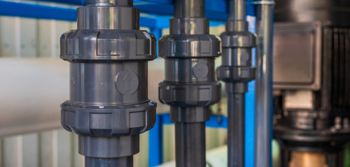
Figure 1: Check valve
Check valves are installed in fluid systems to prevent backflow and protect sensitive equipment, compressors, pipes, and pumps. However, check valves cannot function properly if they are installed incorrectly. Installation errors can lead to valve leakage and failure, compromising the integrity of the entire piping system. This article discusses the check valve’s installation position and process in detail.
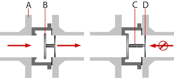
Figure 2: Spring-loaded in-line check valve open (left) and closed (right). The working components are the valve body (A), disc (B), spring (C), and guide (D).
Table of contents
Check valve installation guidelines
Keep the following installation guidelines in mind when selecting a check valve to ensure you acquire the right valve for your system:
- Selection: Choose the check valve according to the pipe’s size, media compliance, and flow rate. Choosing the wrong valve can result in premature wear and tear and component failure.
-
Positioning:Ensure the valve is on a straight run of pipe. There should be 5 pipe diameters before and 10-15 diameters after the valve. This ensures a steady flow through the valve.
- For example, if the pipe is 1" in diameter, ensure there is 5" of straight pipe in front of the check valve and 10" - 15" of straight pipe after the check valve.
- Horizontal vs vertical piping: Many check valve designs are only suitable for horizontal installation, e.g., swing and lift check valves. Horizontal installation is always best because it minimizes the effects of gravity. However, only spring-assisted axial flow check valves are suitable when vertical installation is necessary due to vertical piping.
- Orientation: Note the arrow on the check valve pointing towards the media flow direction (Figure 3). The arrow is usually printed on a separate tag or marked on the valve body.
-
Material: Select a valve made of material that is similar to the pipe to minimize galvanic and electrical potential differences. For example:
- Brass valves work well with copper pipe
- Stainless steel does not work well with copper pipes. If necessary, you can use plastic fittings as an intermediary between the valve and pipe.
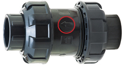
Figure 3: Check valve. The circled arrow shows the direction of media flow
How to install a check valve
1. Turn off fluid supply
If installing the check valve into an operating system, turn off the fluid supply to the piping or tubing where it will be installed.
2. Check valve and pipe evaluation
Check for foreign particles within the valve, as they can disrupt the smooth flow of media through it. Also, check for uneven edges, scratches, or anything else that could prevent the check valve from sealing properly.
For example, in the case of swing valves, move the flapper by pushing it away from the seating surface to ensure it moves freely. Also, ensure the pipes are clean and debris-free before installing the check valve.
3. Check valve placement
An arrow on the valve indicates the flow direction. Position the valve accordingly on the pipeline (horizontal or vertical).
4. Attach the check valve
Attach the check valve to the pipeline. There are many types of connections. The following provides general guidance on installing the check valve based on the connection type. Read our available articles on the various connection types to learn more.
Compression ring
Installation advice:
- Ensure the pipe ends are clean and free from burrs.
- Slide the compression nut and ring onto the pipe.
- Insert the pipe into the valve body until it reaches the stop.
- Tighten the compression nut by hand, then use a wrench to secure it further. Avoid overtightening to prevent damage.
- Read our compression ring guide for more information
Figure 4: A check valve with compression ring connection type
Flange
Installation advice:
- Align the valve flanges with the pipe flanges.
- Insert the gasket between the flanges to ensure a proper seal.
- Insert bolts through the aligned holes and hand-tighten nuts.
- Use a torque wrench to tighten the bolts in a crisscross pattern to the specified torque.
Figure 5: A check valve with flange connection type
Glued sleeve
Installation advice:
- Clean and dry the pipe ends and valve sockets.
- Apply a suitable solvent cement to both the pipe and the valve socket.
- Insert the pipe into the valve socket with a twisting motion to ensure even distribution of the cement.
- Hold in place until the cement sets, following the manufacturer's curing time.
Figure 6: A check valve with glued sleeve connection type
Hose pillar/barb
Installation advice:
- Slide a hose clamp onto the hose.
- Push the hose onto the valve's hose pillar/barb fitting.
- Position the hose clamp over the fitting and tighten it securely with a screwdriver or wrench.
Figure 7: A check valve with hose pillar/barb connection type
Threaded (inner and outer)
Installation advice:
- Apply thread sealant or PTFE (Teflon) tape to the male threads. Note: Thread sealant or Teflon tape is not necessary on union connections or connections with gaskets (e.g., water tube to bathroom sink)
- Align the valve with the pipe and hand-tighten.
- Use a wrench to tighten further, ensuring not to overtighten to avoid damaging the threads.
- Learn more about thread connections in our thread standards article.
Figure 8: A check valve with threaded connection type
Push in
Installation advice:
- Ensure the pipe end is clean and cut squarely.
- Push the pipe into the valve fitting until it reaches the stop.
- Pull back gently to ensure the connection is secure.
- Some systems may have a locking mechanism; engage it if applicable.
- Learn more in our article on pneumatic push in fittings.
Figure 9: A check valve with push-in connection type
Cutting ring
Installation advice:
- Slide the nut and cutting ring onto the pipe.
- Insert the pipe into the valve body.
- Tighten the nut to compress the cutting ring, which will bite into the pipe, creating a seal.
- Use a wrench to ensure the nut is securely tightened.
- Learn more in our article on cutting ring fittings.
Figure 10: A check valve with cutting ring connection type
Victaulic connections
Installation advice:
- Ensure the pipe ends are grooved according to specifications.
- Align the valve with the pipe ends.
- Place the gasket over the pipe ends and align it with the valve.
- Position the coupling housing over the gasket and pipe ends.
- Insert the bolts and nuts, and tighten them evenly using a wrench.
Figure 11: A check valve with vitaulic connection type.
5. Testing the check valve
Turn on the fluid supply to the check valve and let it pass through the valve to test its functionality. If the water gets blocked during testing, double-check the direction in which the valve is installed. If the check valve leaks or any other issue arises, troubleshoot using the tips mentioned in the next section.
Check valve maintenance
Check valves do not require much maintenance, but they can be kept working more effectively by consistently checking them for leaks, rust, debris, and optimum flow.
- Clean the check valve thoroughly when it is ready for maintenance; the cleaner, the better.
- Try to follow the valve manufacturer’s maintenance instructions. This is particularly helpful if the manufacturer has special requirements.
FAQs
How to install a check valve?
There are various ways to install a check valve depending on its connection types. For example, threaded, hose barb, vitaulic, push-in, and glued sleeve.
Can a check valve be installed horizontally?
Yes, a check valve can be installed in both vertical and horizontal pipe runs. However, swing check valves should be installed horizontally only.


