


Pneumatic Solenoid Valves
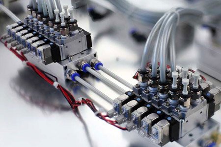
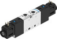
Figure 1: Pneumatic solenoid valves on a manifold.
Pneumatic solenoid valves use electromagnetic force to control compressed air across numerous industrial applications. They offer consistency, quick response, and a versatile design, making them ideal for automation. Whether in assembly lines, material handling, or fluid distribution, these valves maintain operational stability and reduce energy use by precisely regulating flow to pneumatic cylinders, valves, air tools, and more. This article discusses their basic design, operating principles, and the different types available.
Table of contents
View our selection of pneumatic solenoid valve products here!
Design and operating principle
Most pneumatic solenoid valves have an aluminum body; a few have a stainless steel body, plastic, or a combination of aluminum and plastic. These valves generally have a spool design (learn more in our poppet vs spool valve article), which operates by having a sliding spool within the valve that has several seals along its length. Sliding the spool back and forth allows different ports to be connected or closed off.
To create a sealing with absolutely no leakage is very difficult with the spool design. Therefore, pneumatic solenoid valves always have a very small (but acceptable) internal leakage.
Moving the spool needs little force; air pressure doesn't affect it much. Also, the force of the spring in mono stable valves is quite small. As a result, the solenoids usually consume a low amount of power. Because most valves are pilot operated, the required force of the solenoid is even less.
Pilot operation means the valve uses air pressure to work, controlled by a solenoid. The valve can be internally or externally piloted.
-
Internally piloted valves:
- Use the inlet pressure to actuate the valve.
- Require a certain differential pressure, typically between 0.1 - 1.5 bar, to operate.
- Will not switch state if the pressure is too low when the solenoid is actuated.
- Not suitable for use in low-pressure systems or vacuum applications.
-
Externally piloted valves:
- Use a separate channel for the pilot operation.
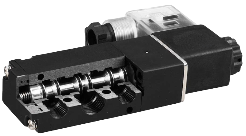
Figure 2: Section view of a 5/2-way solenoid valve. In the valve body is a movable spool with seals. Different ports on both sides of the valve body are connected or closed off by sliding the spool from left to right.
Is air the only media you can use?
Sometimes, engineers ask if a pneumatic solenoid valve can be used for other media, such as water or oil. The short answer is that it is not recommended. Many pneumatic solenoid valves are internally piloted and vent a minimal amount of air required to actuate the valve. A small air leak is usually OK, but not for water, oil, or other media.
Furthermore, the valve materials are optimized for use with air. Usually, the valve is made of aluminum parts and NBR or HNBR seals. Other media than air might cause corrosion or other chemical reactions, which can negatively impact the valve's lifespan.
Mono-stable and bi-stable valves
- Mono-stable solenoid valve: A mono-stable valve, also known as a single-acting solenoid valve, is held in its home position by a spring and switches to its energized state when actuated; it returns to its home position when the power is released.
- Bi-stable solenoid valve: A bi-stable valve, also known as a double acting pneumatic solenoid valve, can be switched by a momentary operation and remains in position after the operation stops; it typically has a solenoid on both ends, with each solenoid responsible for switching to a single state.
Valve types
Pneumatic solenoid valves are assigned two numbers. The first number shows how many ports the valve has, and the second number is the number of states.
For example, a 2/2-way valve has two ports (in/out) and two states (open/closed). A 5/2-way valve has five ports and two states. Pneumatic solenoid valves usually have two, three, or five ports. This section explains each type in more detail.
2/2 way pneumatic solenoid valve
The most common and most simple valve is the 2/2-way valve. It has two ports and two states (open and closed) and is also called a shut-off valve. 2/2-way valves, mono-stable or bi-stable, are used to periodically shut off air supply in pneumatics.
Bi-stable 2/2-way valves usually have one solenoid and are pulse-operated to switch states. These valves are also referred to as latching. Mono-stable 2/2-way valves can be normally closed (opens when actuated) or normally open (closes when actuated).
The majority of 2/2-way solenoid valves are mono-stable and normally closed. The image below shows the symbol for a normally closed valve.
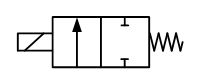
Figure 3: Circuit function of a normally closed 2/2-way solenoid valve
3/2 way pneumatic solenoid valve
A 3/2-way valve has three ports and two states. It is used, for instance, to control a single-acting cylinder. The valve fills the cylinder and vents it afterward to realize a new working stroke. Therefore, a valve with two ports would not be sufficient. A third port is required for venting.
3/2-way valves can be mono-stable or bi-stable. Like 2/2-way valves, mono-stable 3/2-way valves can be closed or open. The pneumatic solenoid valve diagram below represents a mono-stable 3/2-way normally closed.
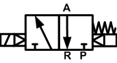
Figure 4: Circuit function of a NC 3/2-way solenoid valve
5/2 way pneumatic solenoid valve
A 5/2-way valve has five ports and two states. It is used, for instance, to control double-acting cylinders, which require two outlet ports of the valve. 5/2-way valves can be mono-stable or bi-stable.
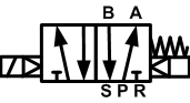
Figure 5: Circuit function of a 5/2-way solenoid valve
5/3-way valve
5/3-way solenoid valves have three states. The third state is used to stop a double-acting cylinder in an intermediate position. These valves are mono stable and return to the center position when the solenoids are not energized. Two solenoids are used to switch the valve to the other two states.
5/3 valves are available in three variants: with a closed center position, a venting center position, and a pressurized center position. The closed center valve is represented by the symbol shown below.
Figure 6: Circuit function of a centre closed 5/3-way solenoid valve
Namur standard
Many pneumatic solenoid valves have a standardized flange design that can be mounted directly to appliances such as a pneumatic actuator. The most common standard is the NAMUR standard (VDI/VDE 3845), a European standard that defines a standard interface to mount pneumatic solenoid valves directly to the rotary actuator. This standard is adopted worldwide. The valves are mounted on the actuator with M5 screws.
Actuators produced in the USA generally have #10-24 threads. The valve is provided with two O-rings to seal the port connection between the valve and the actuator. The interface design allows the valve to be mounted in two positions by rotating it 180 degrees. This changes the actuator's rotation in relation to the energization of the control valve.
Figure 7 shows the dimensions for a valve with G1/4" and G1/2" ports.
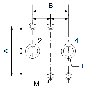
| T | A | B | M |
| G1/4" | 32 | 24 | M5 |
| G1/2" | 45 | 40 | M6 |
Figure 7: Dimensional drawing for the NAMUR standard flange.
FAQs
What is a pneumatic solenoid valve?
A pneumatic solenoid valve is an electromechanically operated valve used to control the flow of air in pneumatic systems.
How does a pneumatic solenoid valve work?
A pneumatic solenoid valve works by using an electric current to energize a solenoid coil, which moves a plunger to open or close the valve.
What is a 3/2 way pneumatic solenoid valve?
A 3/2 way pneumatic solenoid valve has three ports and two positions, used to control the flow of air to actuate devices like cylinders.
What is a 5/2 way pneumatic solenoid valve?
A 5/2 way pneumatic solenoid valve has five ports and two positions, typically used to control double-acting cylinders.


