


How To Install a Flow Meter
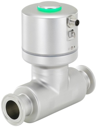
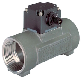
Figure 1: A SAW flow meter (left) and paddle wheel flow meter (right).
Accurate flow meter installation ensures precise flow meter measurements, which is fundamental in numerous industrial applications. This article is a comprehensive guide to flow meter installation, focusing on the key considerations and best practices that ensure optimal performance and accurate readings. It covers various flow meter types (e.g., ultrasonic, electromagnetic, and paddle wheel).
Table of contents
- Pre-installation considerations
- Installation process
- Post-installation considerations
- Flow meter type installation specifics
- FAQs
View our online selection of flow meters!
Pre-installation considerations
This section covers general flow meter installation guidelines for many different types of flow meters. Specific flow meters from specific brands may have installation requirements not discussed here. Always read a specific meter's installation instructions carefully before attempting to install.
- Pipe conditions: The flow meter should be installed in a section of pipe that is always full of liquid. Avoid installing at high points in the piping system to prevent the presence of trapped air.
- Location: Choose a site where the flow meter will not be subjected to extreme temperatures or vibrations. Ensure easy accessibility for maintenance and reading.
- For electromagnetic flow meters, also avoid locations with magnetic interference.
- Straight pipe requirements: To avoid flow disturbances, install the flow meter in a straight run of pipe with a minimum length of straight piping upstream and downstream from the meter, according to the manufacturer's recommendations. A general rule of thumb is to have a minimum distance of 3 times the pipe diameter (3 x DN) upstream and a minimum distance of 2 times the pipe diameter (2 x DN) downstream from any interfering elements.
Figure 2 shows the flow through an elbow connector. The elbow creates a heavily asymmetric velocity profile (Figure 2 labeled A), which should be fixed using straight pipe lengths (Figure 2 labeled B) before the fluid arrives at the flow meter. The flow meter should be installed where the velocity profile is symmetrical (Figure 2 labeled D).
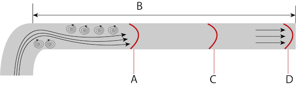
Figure 2: The effect of an elbow on flow stream: heavily asymmetric velocity profile (A), straight pipe length (B), slightly asymmetric velocity profile (C), and symmetrical velocity profile (D).
- Flow conditioners: Flow conditioners are used when sufficient lengths of straight pipe are not feasible. Flow conditioners are devices positioned inside the pipe parallel to the flow direction (Figure 3). They consist of tubes or vanes that guide the fluid molecules to travel straighter paths, stabilizing the flow before it reaches the flow meter.
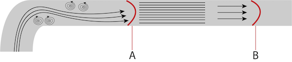
Figure 3: Effect of flow conditioners: asymmetric velocity profile (A) and symmetric velocity profile (B).
- Chemical compatibility: Verify that the materials of the flow meter are compatible with the fluid being measured to avoid corrosion or degradation. Learn more in our material chemical resistance article.
Installation process
- Preparation: Turn off and isolate the piping system. Drain and clean the section where the flow meter will be installed.
- Inspection: Before installation, inspect the flow meter for any damage incurred during shipping or handling.
-
Location environment: Ensure the installation location is not in direct sunlight and the ambient temperature is within the range recommended by the manufacturer.
- Water protection: If the meter has an IP65 protection rating, do not install the meter underwater. If the rating is IP67, do not install the meter below 1 meter of water. If the rating is IP68, do not install the meter below 5 meters of water.
-
Positioning: Ensure the flow meter is installed in the correct orientation concerning the flow direction, which is typically indicated by an arrow on the body of the meter.
- Horizontal: Air bubbles usually get trapped at the top. If the water pressure is not very strong and the pipe doesn't fill up quickly, it's best to install the meter at the lowest part of the pipe (Figure 4).
- Vertical: With flow meter vertical installation, the flow should go up through the meter rather than down. Upward flow is more stable than downward flow, so the meter will give a more precise measurement (Figure 5).
Figure 4: When installing a flow meter in a horizontal position, ensure the meter is installed at a low point (A) rather than a high point (B). This prevents air bubbles from interfering with the meter's readings.
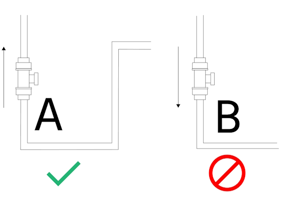
Figure 5: When installing a flow meter vertically, ensure the flow direction is up through the flow meter instead of down. This ensures a steadier flow and more accurate meter readings.
-
Mounting
- Flanged: Mount the flow meter between the flanges, ensuring that it is properly aligned with the pipeline. Use gaskets between the meter and the flanges to prevent leaks.
- Threaded: Ensure the flow meter's threads match the same standard as the pipe threading (e.g., NP and BSP)
- Lubrication:LubricateO-rings with a non-petroleum-based lubricant for smooth insertion and sealing.
- Clamp-on: Secure the flow meter to the pipe using clamp-on fixtures, ensuring a snug fit without over-tightening. Verify that the meter is level and the sensors are in direct contact with the pipe surface for accurate readings. Use appropriate coupling gel to enhance sensor-pipe acoustic coupling if necessary.
-
Reducers: If a reducer is required, ensure that the inner angle does not exceed 7.5°. To determine the minimum length needed to maintain the angle below 7.5°, use the following formula:
L = (D – d) x 7.63
L represents the minimum length required, D represents the larger diameter, and d represents the smaller diameter of the reducer. By calculating this length, the user can ensure that the reducer's inner angle remains within the recommended limit, minimizing flow disturbances and maintaining accurate measurements.
Example: If a flow sensor with dimension DN 50 is mounted downstream of a 90 mm pipe, the reducer must have a minimum length of 305 mm to keep the inner angle below 7.5°.
- Connection: Tighten the flange bolts in a criss-cross pattern to ensure even pressure and to prevent damage to the flow meter.
- Electrical connections: Connect the power supply and output signal cables according to the wiring diagram provided by the manufacturer. Ensure all connections are secure and watertight. Meters may provide pulse, voltage, or current outputs that can often be interfaced to a PC using a USB port.
- Grounding: Connect the grounding cable from the flow meter to the grounding system of the plant to prevent electrical noise and ensure accurate readings.
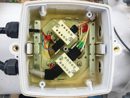
Figure 6: Electromagnetic flow meter circuit connectors
Post-installation considerations
- Verification: Check for leaks around at the connection points and ensure that the flow meter is not subjected to any stress from the piping.
- Calibration: Perform a zero calibration with the pipe empty and then with the pipe full, following the manufacturer's instructions. Read our articles on electromagnetic flow meter calibration and paddle wheel flow meter calibration to learn more about those specific flow meter types.
- System checks: Turn on the system and verify that the flow meter is operating correctly. Check the flow rate readings and compare them to expected values.
- Documentation: Record the installation details, including date, location, and any calibration data, for future reference and maintenance.
- Transmitter location: The flow meter's transmitter, which sends the flow data, should be placed appropriately in relation to the pipe to ensure efficient and reliable communication.
Flow meter type installation specifics
-
Electromagnetic flow meters:
- Electromagnetic flow meter installation requires a conductive fluid to operate properly.
- Must be installed in a section of pipe that is full of liquid (not suitable for gasses or steam).
- Grounding rings may be necessary if the pipes are non-conductive.
-
Paddle wheel flow meters:
- The paddle wheel should be installed where the flow is laminar and not affected by turbulence.
- Orientation can be critical; some models require horizontal installation, while others can be vertical.
-
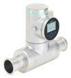
SAW (Surface Acoustic Wave) flow meters:
- Non-intrusive installation, with sensors mounted on the outside of the pipe.
- Require a specific pipe material and wall thickness to ensure proper signal transmission. Learn more in our Burkert 8098 flow meter article.
- No flow conditioning required, but the installation area should be free from heavy vibration and temperature extremes.
-
Coriolis flow meters:
- With coriolis flow meter installation, the meter needs to be installed in a way that prevents the accumulation of air or gas pockets in the measuring tubes.
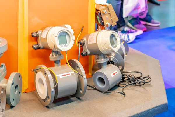
Figure 7: Electromagnetic flow meters being prepared for installation.
FAQs
What should you consider while installing a paddle wheel flow meter?
Ensure proper pipe length, orientation, secure mounting, and calibration per manufacturer's instructions.
What is needed for paddle wheel flow meter installation?
Tools, a suitable pipe section, mounting hardware, and calibration equipment are necessary.
Can a paddle wheel flow meter be installed vertically?
Yes, but ensure upward flow to prevent sediment accumulation.
How do I choose the right size flow meter for my application?
To choose the right size flow meter, consider factors such as the flow rate, pipe diameter, fluid properties, and the accuracy requirements of your application.
Can I install a flow meter on an existing pipeline without interrupting the flow?
In some cases, this is possible by using techniques such as hot tapping or clamp-on flow meters, but it is crucial to consult a professional and consider the specific requirements of your application.
How do you install a magnetic flow meter?
Install a magnetic flow meter in a straight run of pipe with suitable environmental conditions. Follow the manufacturer's specific instructions and recommendations.
What is the installation position of a magnetic flow meter?
A magnetic flow meter can be installed horizontally or vertically. If vertically, ensure the media flow will go up through the meter instead of down.

