


Burkert 8098 Flow Meter
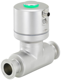
Figure 1: Burkert 8098 FLOWave L flow meter
The Burkert 8098 flow meter is based on SAW (Surface Acoustic Waves) technology and designed for applications with high hygienic demands. It is a multi-parameter device that measures the temperature and density or detects solids or bubbles in the media. It is commonly used in industries such as food and beverage, pharmaceuticals, and biotechnology. The main features of the Burkert 8098 flow meter include:
- Stainless steel materials and hygienic body design
- Measuring tube free of additional wetted parts
- Zero pressure drop
- Lightweight, compact, and easy-to-clean design
- Compliance with multiple standards
- Optimal measurement results with homogeneous liquids, free of air and solid particles
- Integrated viscosity compensation for liquids with high viscosity
- Optional density measurement feature to calculate mass flow based on volume flow and density measurements
Table of contents
- Product design
- Working principle
- Operation principle
- Special function
- Certifications
- Product properties
- Installation
- Mounting options
- Accessories
- Applications
View our online selection of SAW (Surface Acoustic Waves) flowmeters!
Product design
A Burkert 8098 flow meter consists of a flow sensor and a transmitter. The flow sensor includes a measurement tube equipped with interdigital transducers, a sensor housing, and process connections that conform to ISO, ASME BPE, DIN, and SMS standards. The sensor size options range from DN 08 to DN 80 (⅜" to 3" in diameter). The 8098 flow meter is available in two types:
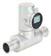
- FLOWave L flow meter: The FLOWave L flow meter consists of a flow sensor Type S097 and a FLOWave L transmitter. It is available with or without a display. If equipped with a display, it features a high-resolution screen and a capacitive working keypad for user interactions. The user-friendly menu system guides users through various actions. The flowmeter provides analog as well as digital outputs. Additionally, a third output signal can be switched between analog and digital based on parameter settings. Electrical connections are made using push-in connectors via two cable glands and/or one M12 circular connector.
- FLOWave S flow meter: The FLOWave S flow meter consists of a flow sensor Type S097 and a FLOWave S transmitter. This variant does not come with a display, and the data can be accessed through a proper software interface. It only has an electrical connection available through an M12 circular male connector.
Working principle
The flow sensor, which includes interdigital transducers, measures the propagation time of Surface Acoustic Waves in the fluid (discussed later). The transmitter receives this information from the flow sensor and processes it to provide various measurements, such as volume flow rate, density, and mass flow rate.
The transmitter is equipped with electronic circuitry that converts the measurement data into digital signals. These signals are transmitted through various communication protocols, such as analog outputs (e.g., 4 - 20 mA) or digital outputs (e.g., Modbus, PROFIBUS, or Ethernet protocols). The specific communication options depend on the chosen configuration and model of the Burkert 8098 flow meter. The transmitted data can be utilized by other devices, such as control systems or data acquisition systems, for further analysis, monitoring, or process control. The flow meter cannot measure gas and steam, but their flow does not negatively affect the device or its operation.
Operation principle
FLOWave works on the principle of Surface Acoustic Waves (SAW), which are similar to earthquake wave propagation. Interdigital transducers are positioned on the flattened regions of the tube's surface, functioning as both emitters and receivers. Transducers 1 and 4 transmit waves in the direction of the liquid flow, while transducers 2 and 3 send waves in the opposite direction. The propagation time from the emitter to the receiver is measured, and the difference between the forward and backward propagation times correlates directly with the volume flow rate.
Mass flow measurement
Mass flow is determined by calculating the fluid density and volume flow. Mass flow and density measurements are optional features in the standard FLOWave flowmeters but require adjustment and calibration during production. Consequently, it is crucial to specify the desired features when ordering the device.
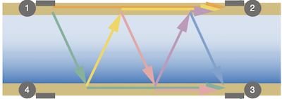
Figure 2: FLOWave operation principle
Special function
The 8098 flow meter has features for identifying gas bubbles and solid particles, relying on two aspects: the acoustic transmission factor (ATF) and the differentiation factor (DF).
- The ATF is a metric that continuously varies from 5% to 120%. The value is proportional to and affected by the presence of gas bubbles and solid particles.
- The DF is another metric that aids in the detection and distinction of various liquids, with a measurement range of 0.8 to 1.3. This value is continuously measured and compensated for the temperature to account for temperature changes. The DF value is established by comparing the measured liquid to water, which acts as a reference fluid. By monitoring shifts in the DF value throughout the measurement process, it is possible to differentiate between different liquid types.
Certifications
Burkert 8098 flow meter comes with multiple certifications as discussed below:
Certifications
- EHEDG (Type EL CLASS I): Ensures compliance with hygienic design standards for food, beverage, and pharmaceutical industries
- 3A (28‑06): Indicates compliance with strict sanitary standards for industries like food processing and dairy
- On request: UL (for USA and Canada) and ATEX/IECEx: Essential for safety and performance in hazardous environments in the US and Canada.
Certificate
- FDA declaration of conformity: Confirms suitability for food, beverage, and pharmaceutical applications
- Inspection certificate 3.1: Provides material traceability and compliance verification
- Certification of compliance ASME BPE
- Fluidic test report (test regarding Volumetric flow rate or volume and mass flow rates, if density and mass flow rate option chosen)
On request:
- Calibration certificate (volumetric flow rate, volume, mass flow rates, and density)
- USP class VI declaration
- ECR1935/2004 declaration
- CRN 0C21751 declaration
- Test report 2.2
- Certification of conformity for the surface quality DIN 4762, EN ISO 4287, EN ISO 4288 – Certification of conformity for passivation and electro-polishing processes
- MTBF (Mean Time Between Failures) manufacturer declaration: Provides an estimate of product reliability over time
Product properties
Materials
Before using the Type 8098 flow meters, ensure that the device materials are compatible with the fluid in use.
-
Non-wetted parts sensor housing:
- For a sensor with process connection ≤ DN 50/2": Stainless steel 304/1.4301
- For sensor with process connection > DN 50/2": Stainless steel 316L/1.4435
-
Wetted Parts Measurement Tube and Process Connection:
- Stainless steel 316L/1.4435 with low delta ferrite content
-
Surface Quality Measurement Tube (Inner Surface):
- Ra <0.8 µm (30 µin.) or
- Ra <0.4 µm (15 µin.) (electro-polished) according to ISO 4288
Ra is a measure of the average deviation of surface roughness within a sampling length. It indicates the smoothness or roughness of the surface texture. The lower the Ra value, the smoother the surface. Read our overview article to learn more about the stainless steel 304 and 316.
Measurement range
- Volume flow rate measurement: The flowmeter can measure the volume flow rate ranging from 0 to 1.7 m³/h up to 0 to 200 m³/h.
- Density measurement: The flowmeter can measure density in the range of 0.8 to 1.3 g/cm³. However, this feature is inactive by default.
- Mass flow rate measurement: The mass flow rate measurement range is from 0 to 1,360 kg/h up to 0 to 260,000 kg/h. This feature is inactive by default.
- Temperature measurement: The flowmeter is capable of measuring temperatures between -20°C to 140°C (-4°F to 284°F).
- Special function: The flowmeter has an active special function that can be switched off. This function includes the Acoustic Transmission Factor (ATF) and Differentiation Factor (DF).
Installation
The FLOWave flow meter is calibrated at the factory under specific conditions, where the distances between the inlet and outlet are 40 times the pipe's diameter (40xDN) and 1 time the pipe's diameter (1xDN), respectively. The internal pipe diameter is also taken into account during calibration. If the actual installation conditions deviate from these reference conditions, the user can easily adjust the flow meter using the built-in K factor adjustment or the Teach-in procedure. These adjustment procedures help correct any differences in distances or pipe diameters, ensuring accurate flow measurement in different installation setups. Read the flow meter 8098 manual for more details on the operating instructions and the usage techniques.
Selecting pipe diameter
The graph in Figure 3 helps determine the appropriate pipe size and flowmeter for a specific application based on the fluid velocity and flow rate. The appropriate pipe diameter can be determined by looking at the intersection of the flow rate and flow velocity on the chart.
- Example: For a flow meter with a flow of 10 cubic meters per hour, and an optimal flow rate of 1 to 3 meters per second, the result would be to select a pipe size of either DN 40 or DN 50.
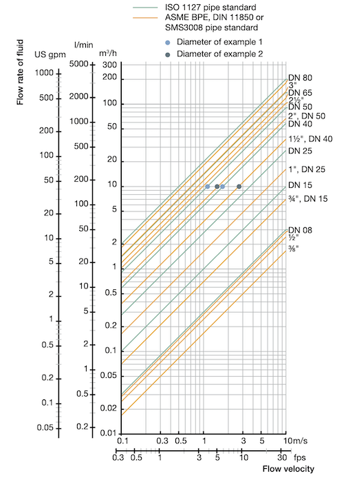
Figure 3: Graph for selecting pipe diameter for Burkert 8098 flow meter
Mounting options
FLOWave L flowmeter
The transmitter position can be changed in steps of 90 degrees. The display module and the blind cover are locked for safety, which can be unlocked with the magnetic key included along with the device.
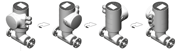
Figure 4: FLOWave L flowmeter mounting options
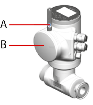
Figure 5: Magnetic key (A) and the display module (B) in FLOWave L flowmeter
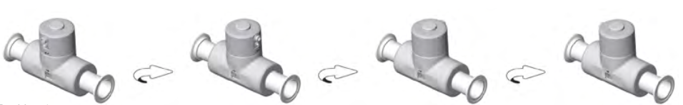
Figure 6: FLOWave S flowmeter mounting options
Accessories
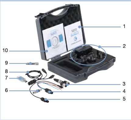
Figure 7: Flow meter 8098 accessories: Quick start(1), power supply (2), büS terminating resistor (3), circular male connector (4), büS connection cable (5), büS adapter (6), büS stick (7), büS service cable (8), magnetic key (9), and CD (10).
As seen in Figure 7, the various accessories available with Burket 8098 flow meter are:
- 1: Quick-Start
- 2: Power supply: 100…240 V AC/ 24 V DC 1 A and adaptors for power supply worldwide use
- 3: büS terminating resistor on büS Y-splitter
- 4: 5-pin M12 circular male connector wired on free end cable
- 5: büS connection cable with 5-pin M12 circular male connector, micro USB B plug
- 6: büS adapter with 5-pin M12 circular male connector, A-coded to 5-pin M12 circular male connector, A-coded
- 7: büS stick (USB to büS/CANopen adaptor)
- 8: büS service cable with 5-pin M12 circular female connector, mini USB, and circular plug-in connectors for power supply
- 9: Magnetic key
- 10: CD - Communicator
Applications
The Burkert 8098 flow meter is designed for highly hygienic applications:
-
Clean-in-place (CIP) systems:
- Integrated into CIP systems for cleaning and sanitizing processing equipment
- Provides accurate flow measurements during CIP cycles
- Ensures effective cleaning and efficient use of cleaning agents
-
Dairy industry:
- Measures the flow of milk and dairy products
- Suitable for milk reception, processing, and packaging applications
-
Brewing and beverage industry:
- Measures the flow of liquids in breweries and beverage production
- Used for water, wort, beer, and soft drink flow measurement
-
Pharmaceutical and biotechnology applications:
- Suitable for sterile conditions and accurate flow measurement
- Used in drug manufacturing, bioreactors, and sterile filtration
Read our flow meter calibration and verification article for more information on how to calibrate a flow meter.
