


Compressor Unloader Valves
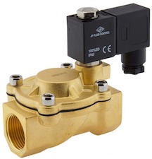
Figure 1: Air compressor unloader valve
An air compressor unloader valve releases trapped air from the compressor's compression tank and discharge line when the motor stops, allowing for an easier restart. There are two main types of air compressor unloader valves: electrical and mechanical. Extracting the air is essential for the compressor motor to start again with minimal effort. If the air is not removed, the load generated by the trapped air in the compression chamber and tank discharge line creates a high initial torque that the motor may struggle to overcome. Figure 1 shows an example of an electrical air compressor unloader valve.
Table of contents
- How does an air compressor unloader valve work?
- Types of air compressor unloader valves
- Mechanical vs solenoid unloader valves
- Selection criteria for electrical unloader valve
- How to install an unloader valve on an air compressor
- Solving common problems
- FAQ
View our online selection of compressor unloader valves!
How does an air compressor unloader valve work?
The function of an unloader valve in an air compressor is to release the remaining air from the compression chamber and relative lines when the motor turns off. The operation of an air compressor is explained in the diagram in Figure 2 to understand how this valve works.
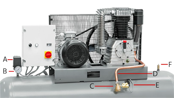
Figure 2: Air compressor components, pressure switch (A), pressure gauge (B), check valve (C), tank discharge line (D), unloader valve (E), and safety valve (F).
An air compressor has the following operating principles:
- Before the compressed air reaches the tank, it passes through a pressure switch (Figure 2 labeled A) that evaluates the pressure between maximum and minimum established limits.
- While the compressor works, the tank accumulates compressed air until the pressure reaches its pre-set maximum.
- Upon reaching its maximum pre-set value, the tank's pressure exerts a force on an internal piston of the pressure switch, moving it up, separating its contacts, and shutting off the motor.
- The air in the compressor chamber and the tank discharge line (Figure 2 labeled D) is immediately released into the atmosphere through the unloader valve (Figure 2 labeled E).
- This action closes the check valve (Figure 2 labeled C) and prevents the air contained in the tank from escaping.
- Once the tank pressure reaches its minimum, the pressure switch (Figure 2 labeled B) contacts come back together, and the motor starts again.
Types of air compressor unloader valves
Although compressor unloader valves vary depending on the compressor type and manufacturer, there are two main types: mechanical and electrical.
Mechanical unloader valves
This type of unloader valve works according to the pressure differential. It opens when the pressure reaches a predetermined pressure value. Figure 3 shows a mechanical compressor unloader valve diagram.
Figure 3, step A, shows air from the compressor entering the mechanical unloader valve through the inlet (1), traveling through the unloader valve chamber (2) to the non-return valve (5). The force exerted by the air pushes open the non-return valve, allowing compressed air to go to the storage tank through the outlet (6) and also towards the diaphragm chamber (3) through the passage (4). As the tank fills with compressed air, the pressure increases until it reaches its maximum limit.
At step B, the diaphragm (7) lifts and allows air to pass into the upper chamber (8) of the piston (9). The air entering this chamber pushes the piston down, which allows the air trapped in the unloader valve chamber to be discharged into the atmosphere through the outlet (10). Due to the pressure drop, the non-return valve closes automatically.
Figure 3, step C, shows that when the non-return valve closes, the air that goes towards the upper diaphragm of the valve decreases, the thrust force is low, and the diaphragm closes again. This causes the air trapped on the main piston to be released through the governor exhaust (11) at the top of the air compressor unloader valve (12).
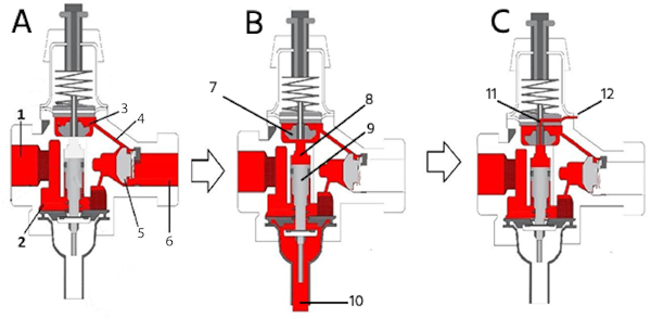
Figure 3: Mechanical unloader valve diagram: inlet (1), unloader valve chamber (2), diaphragm chamber (3), passage (4), non-return valve (5), outlet (6), diaphragm (7), upper chamber (8), piston (9), outlet (10), governor exhaust (11), and air compressor unloader valve (12).
Electrical unloader valves
A solenoid valve is an electrically operated device that controls the amount of air that passes through a line. It shuts off, releases, or doses the flow according to the system requirements. Heavier compressors (from 5 kW) often work with a star-delta system to reduce the motor starting current (compared to a direct start). This motor starts with the star connection and then switches from a star to a delta circuit. During starting, the compressor air is unloaded, in the first few cycles, to a free outlet (rather than to the tank) to reduce the required torque of the motor. A solenoid valve is used as an unloader valve.
There are three types of solenoid valves: direct, semi-direct, and indirect acting.
- The direct-acting valve's function depends only on an electromagnetic field created in the solenoid coil to close or open the valve.
- The indirect valve depends on the system pressure differential.
- The semi-direct-acting valve combines the functions of a direct and indirect valve.
In addition, the circuit function of a solenoid valve determines the ports (2, 3, 4-way) and the position of the valve when it is de-energized (open or closed). Read our technical article about solenoid valves for more information.
The 2/2-way pilot-operated valve is the most commonly used solenoid valve for an electrical unloader valve for air compressors. One of the reasons is that this valve type is suitable for larger flows of heavy air compressors compared to direct-acting valves. It is also the valve type with the lowest energy consumption. This valve type is also known as a servo-assisted solenoid valve. Its function depends on the solenoid coil's behavior and the system's pressure differential (at least 0.5 bar is required for operation). Generally, the valve has two connections, one for the inlet and the other for air discharge, as seen in Figure 4.
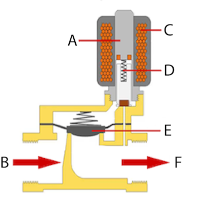
Figure 4: An indirect-type air compressor unloader valve: armature (A), inlet port (B), coil (C), spring and plunger (D), membrane (E), and outlet port (F).
Compressor unloader valve parts
- Armature (A): The metallic cylinder upon which the coil is wound
- Inlet port (B): The air enters the solenoid valve through this port.
- Coil (C): A cylindrical, hollow coil made from enameled copper wire. This coil stores energy in a magnetic field through induction.
- Spring and plunger (D): When no magnetic field exists in the coil, the spring keeps the plunger in a specific position, normally open or closed. The spring yields to force applied to the plunger by a magnetic field.
- Membrane (E): Closing membrane that stops or allows air to be discharged into the atmosphere.
- Outlet port (F): This port releases the air into the atmosphere.
In an indirect solenoid valve, air enters and exits from the inlet connection (Figure 4 labeled E) into the area above the membrane through a control orifice. From there, the air goes to the pilot orifice of the solenoid valve, which is initially closed, as in Figure 5 (left side).
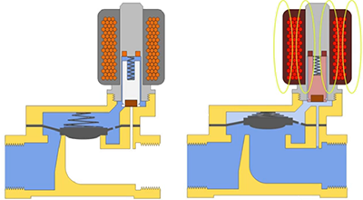
Figure 5: Diagram of a normally closed indirect valve: de-energized (left) and energized (right)
When the tank reaches its maximum pressure, the solenoid coil is energized, and the solenoid valve plunger moves upwards, opening the pilot orifice. With this line open, the pressure of the air housed in the area above the membrane begins to decrease until its value is lower than the pressure exerted by the air over the membrane. Once this membrane moves up, the inlet air passes to the outlet as seen in Figure 5 right. When the tank pressure reaches its minimum limit, the solenoid coil's electrical current stops, and the pilot orifice closes immediately. The air pressure in the membrane's upper chamber is re-established, and the membrane returns to its initial position, preventing air passage from the inlet to the outlet.
A normally closed indirect valve is the most common; it is energized (open) during the star circuit and closed during the delta circuit connection. However, air compressors with the star-delta circuit also use a normally open valve. In this case, the tank pressure reaches its maximum limit, the pressure switch separates its contacts, the motor stops, and the solenoid valve opens (de-energized) to discharge the air into the atmosphere. Once the tank pressure reaches the minimum pressure limit, the pressure switch contacts connect, the motor starts, and the solenoid valve closes (energized) after the connection changes from star to delta, as in Figure 6.
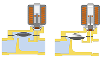
Figure 6: Diagram of a normally open indirect valve: de-energized (left) and energized (right).
Mechanical vs solenoid unloader valves
| Mechanical | Electrical | |
| Adjustment | Can be manually adjusted | Adjusted at the pressure switch or timer |
| Timer | Cannot be operated with a timer | Can be operated with a timer |
| Position | Can be installed in any position | Should be installed upright or with a maximum deflection of 90° |
| Obstructions | Not sensitive to dirt | More sensitive to dirt then a mechanical valve |
| Application | A mechanical unloader valve is commonly used in smaller compressors (less than 5 kW) | In heavier compressors (three-phase motor) the unloader valve used is typically an indirect solenoid valve. |
Selection criteria for electrical unloader valve
In addition to the valve being suitable to work with air, consider the following when selecting a solenoid valve to be used as an air compressor unloader valve:
- Capacity (Kv value): The Kv value determines the airflow through the solenoid valve. Knowing the required Kv value ensures you choose the correct valve with the required capacity. Calculate Kv or Cv values with our valve sizing calculator.
- Maximum operating pressure: The solenoid valve must be capable of handling the maximum working pressure of the compressor.
- Electrical control: Determine whether the valve's voltage is available at the installation site. Check if the system is powered during the air discharging period or if an integrated timer in the valve is used to adjust the opening time. In addition, check if the system requires a normally open or closed valve.
- Connection type and size: Ensure the pipe threads match the solenoid inlet thread type and size. A fitting can be used if the required solenoid valve connection size is unavailable.
- Solenoid valve material: For the valve body, a good choice for a compressed air system is the use of brass as housing material and an FKM (Viton) seal since they have good heat and chemical resistance.
- IP classification: Solenoid valves used in air compressor systems should have an IP65 rating to ensure an effective seal against external agents.
How to install an unloader valve on an air compressor
Installing and wiring a solenoid compressor unloader valve to an air compressor system involves several key steps.
- Safety first: Before starting, ensure the power supply to the air compressor is turned off to avoid any electrical hazards. Also, wear appropriate safety gear.
- Identify the solenoid unloader valve: If replacing an unloader valve, the old one should have two or more wires for electrical connection. It's typically installed near the air compressor's pressure switch. It might be near the check valve attached to the tank discharge line.
- Disconnect the old valve:
- Electrical connections: Carefully disconnect the electrical wires connected to the solenoid coil. Taking a photo or noting the wire connections for reference when installing the new valve is a good idea.
- Remove the old valve: Once all connections are disconnected, remove the old solenoid unloader valve from its mounting. This may involve unscrewing it from a threaded port or removing any clamps or brackets holding it in place.
- Install the new valve:
- Place the new solenoid unloader valve into position. If it screws into a port, ensure it's threaded correctly to avoid cross-threading.
- Install the valve body first. Use a suitable tool for tightening the solenoid valve and another one to hold the system piping.
- Position the valve body so the coil will be upward or with a maximum deflection of 90 degrees to minimize the risk of external agents collecting in the solenoid valve plunger.
- Install the coil. Place it on the valve body, with its gasket and nut over it, and tighten. A guideline for torque is 5 Nm, but the solenoid valve’s manual should have a tightening specification.
- Learn more about this process in our solenoid valve installation article.
- Wiring the solenoid to the pressure switch:
- Connect one wire from the solenoid unloader valve to the pressure switch's load side. This is usually indicated in the pressure switch's wiring diagram.
- The other wire from the solenoid should be connected to a neutral or ground point, depending on the solenoid's requirements.
- Check the compressor motor connection: Ensure that the compressor motor is correctly wired to the pressure switch. The motor should start when the air pressure drops below the switch's low-pressure setting and stop when it reaches the high-pressure setting.
Solving common problems
A malfunction of an air compressor unloader valve can cause leaks if it does not close properly, and even the compressor motor could not start if the valve does not open correctly. The causes and solutions for these common problems are below:
- Dirt in the valve: Sometimes external agents (dust, Teflon, etc.) contaminate the inside of the solenoid valves and cause a device malfunction. To confirm this is the cause of the problem, disassemble the valve, inspect the internal condition, perform a suitable cleaning (if required), reinstall the solenoid valve, and test it to check performance. Checking the upstream lines of the air compressor unloader valve is recommended, too. The dirt could come from another point in the system, and the internal cleaning of the valve could be a momentary solution, but the problem would happen again.
- Internal components damaged: During the internal inspection of a solenoid valve, any piece (membrane, seals, or o-rings) found damaged must be replaced.
- Electrical issues: Confirm that the voltage and frequency are correct. Check the condition of the coil and measure its resistance, in case it tends to zero, this coil is burnt and needs a replacement. Read our technical article about how to replace a solenoid valve coil for more information.
- Valve position: Ensure the valve is installed in the correct orientation with the airflow, by looking at the arrow indication on the valve housing.
FAQ
What does the unloader valve do on an air compressor?
This device is used by air compressors to release to the atmosphere the trapped air inside the compression chamber when the tank pressure reaches its maximum pre-set value.
Does an air compressor need an unloader valve?
Yes, an air compressor needs an unloader valve. Extracting the air by the unloader valve is essential for the compressor motor to start again without any effort.
