


How Welding Regulators Work
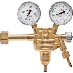
Figure 1: Welding regulator
A welding regulator regulates high-pressure gas from a cylinder to ensure the gas is at the optimal delivery pressure required for a welding application. Without a regulator, inconsistent, excessively high, or low pressure can be dangerous and negatively impact the quality of the weld, resulting in porosity, fissures, or cracks. The consistent pressure produced by the welding regulator ensures the ideal environment for proper welding. Read our pressure regulators overview article to know the design principles, types, and applications of pressure regulators.
Table of contents
- How does a welding regulator work?
- Safety mechanisms on pressure regulators
- Types of welding regulators
- Regulators designed for specific purposes
- Certifications and approvals
- Selection criteria
- Applications
- FAQs
View our online selection of welding regulators!
How does a welding regulator work?
Single-stage welding regulator
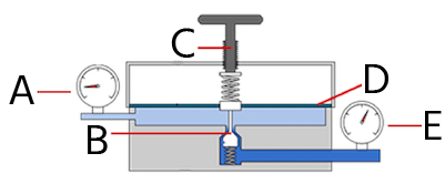
Figure 2: Single-stage regulator: low-pressure chamber gas outlet (A), poppet valve (B), pressure adjustment handle (C), membrane or diaphragm (D), and gas inlet high-pressure chamber (E).
Single-stage pressure regulators reduce the pressure of the media flowing into the regulator to a desired outlet pressure in a single step (Figure 2).
- Gas flows into the high-pressure chamber (E) through the inlet.
- The poppet valve (B) is pushed down by turning the pressure adjustment handle (C). This allows the gas to fill the low-pressure chamber and exert force on the membrane (D).
- The gas exits through the low-pressure chamber outlet (A). The pressure in the low-pressure chamber builds up and forces the valve spring on the pressure adjustment handle to close the poppet valve at the set pressure point.
- The poppet valve and pressure adjustment handle work together to regulate pressure and maintain a steady flow of gas to the welding torch. Pressure gauges monitor the pressure at the gas inlet and outlets.
Dual-stage welding regulator
A dual-stage welding regulator (Figure 3) reduces the pressure of the media flowing into the regulator to a desired outlet pressure in two steps.
- The first stage is non-adjustable and reduces the input pressure to a predetermined intermediate level.
- The second stage is adjustable and delivers the output pressure required by the operator.
For example, the first stage reduces an inlet pressure of 300 bar to 10 bar (4351 - 145 psi). This means that when the user adjusts the regulator, which is part of the second stage, the pressure drops from 10 bar to the desired output pressure and not from 300 bar down to the particular output pressure. Despite variations in inlet pressure, these devices maintain a constant delivery pressure and need fewer readjustments. They are particularly well-suited for high-pressure cylinder applications.
Working principle
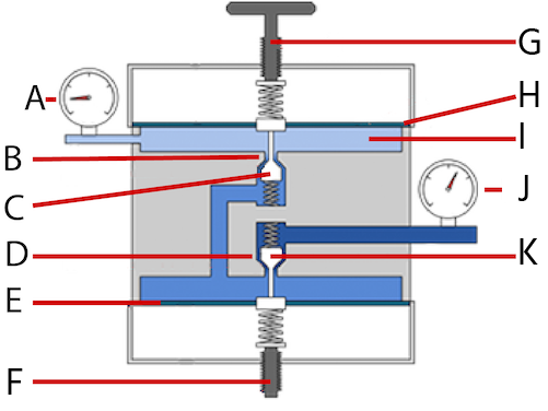
Figure 3: Dual-stage welding regulator: gas outlet (A), first-stage high-pressure chamber (B), second-stage poppet valve (C), second-stage high-pressure chamber (D), first-stage membrane (E), factory-preset pressure valve (F), pressure adjustment handle (G), second stage membrane (H), low-pressure chamber(I), gas inlet (J), and first stage poppet valve (K).
- The gas enters through the inlet (J) and is directed to the first high-pressure chamber (B).
- The factory-preset pressure valve (F) exerts a force on the first-stage poppet valve (K), allowing the gas to pass into the second high-pressure chamber (D) at an intermediate pressure.
- In this second stage, the pressure of the gas within the second high-pressure chamber is further reduced, with the value determined by the pressure adjustment handle (G). The pressure adjustment handle applies pressure to the second stage poppet valve (C). This regulates the amount of gas passing into the low-pressure chamber (I).
- The media ultimately exits through the welding regulator's gas outlet (A). The pressure at the gas inlet and outlet can be monitored using pressure gauges.
Single-stage vs dual-stage welding regulators
A dual-stage welding regulator produces a more stable and consistent output pressure. This is particularly crucial in applications where low pressure is needed for welding, such as torches with a small flame.
When large amounts of gas are consumed, the pressure delivered by a dual-stage regulator remains steady throughout the cylinder's lifespan. This is because, as the pressure in the cylinder decreases, the adjustable second stage of the multi-stage regulator ensures that the delivery pressure remains consistent, unlike a single-stage regulator, which requires frequent adjustments to maintain the desired pressure. However, dual-stage regulators are costly when compared to single-stage regulators.
Safety mechanisms on pressure regulators
Figure 4: Welding
Depending on the model, welding regulators can come with the added functionality of a pressure relief valve or safety disc.
- Pressure relief valve: A pressure relief valve is a device that lowers the pressure to prevent damage to the system. These valves are installed on the low-pressure side of the equipment to prevent damage and unsafe working conditions. The relief valve opens up to relieve pressure when the system pressure exceeds the setpoint or response pressure. Once the pressure reduces to a safe level, the valve re-seats itself in the initial position. Welding regulators developed for inert gasses, air, and CO2 are usually fitted with a relief valve.
- Safety disc: A safety disc consists of a thin metal disc that breaks to release excess pressure. These discs are for one-time use and must be replaced to use the regulator again. Welding regulators developed for fuel gas or flammable gasses (acetylene, propylene, or propane) are usually fitted with safety discs and other safety devices, such as shut-off valves. If a safety device is activated when using the welding regulator, the gas bottle and welding regulator should be switched off and examined. Replace the safety disc if necessary.
Types of welding regulators
Flowmeter regulator
A flowmeter regulator combines a pressure regulator and a flow meter (a device used to measure a fluid's flow rate or quantity, such as gas, liquid, or steam). A flowmeter regulator controls gas flow from the outlet with a fixed outlet pressure and variable orifice. The device is designed to measure and control gas flow through a pipe or conduit by adjusting the size of the orifice (opening) through which the gas flows. The outlet pressure, or the pressure at which the gas exits the flowmeter regulator, is fixed and does not change. On the other hand, the orifice can be adjusted to vary the gas flow through it. This allows for the precise control of the gas flow and ensures that the outlet pressure remains constant, regardless of changes in the flow rate. This type of flowmeter regulator is commonly used in industrial applications such as gas pipelines, chemical plants, and manufacturing facilities to control the flow of gasses such as natural gas and propane.
Dual flowmeter
In welding, a dual flowmeter is typically used to measure and control the flow of two gasses: the shielding gas and the fuel gas.
- The shielding gas, typically argon or a blend of argon and other gasses, is used to protect the weld pool and the surrounding area from oxidation and other forms of contamination.
- The fuel gas, typically acetylene or propane, provides the heat needed to melt the metal and create the weld.
A dual flowmeter for welding typically consists of two flow sensors, one for each gas and a control unit that allows the user to adjust the flow rate of each gas separately. The flow sensors measure the flow of each gas and send the data to the control unit, which then displays the flow rate of each gas on a digital display. The user can then adjust the flow rate of each gas using the control unit, ensuring that the correct amount of each gas is used for the welding process.
Flow gauge regulator
A flow gauge regulator in welding is a device used to measure and control the flow of gasses, typically the shielding gas and fuel gas, used in the welding process. It consists of a flow gauge, which measures the flow of the gasses, and a regulator, which controls the flow by adjusting the opening or closing of a valve. A flow gauge regulator controls the flow of one gas at a time, while a dual flowmeter measures the flow of two different gasses simultaneously.
Working
- The flow gauge measures the shielding gas and fuel gas flow, and displays the flow rate on a gauge.
- The user can adjust the flow rate of each gas using the regulator, which controls the flow by adjusting the opening or closing of a valve.
- The flow gauge continuously monitors the flow of the gasses, and the regulator adjusts the flow rate as needed to maintain the desired flow rate.
The flow gauge regulator ensures that the correct amount of each gas is used for the welding process. This helps maintain a high-quality weld and improves the overall efficiency of the welding process.
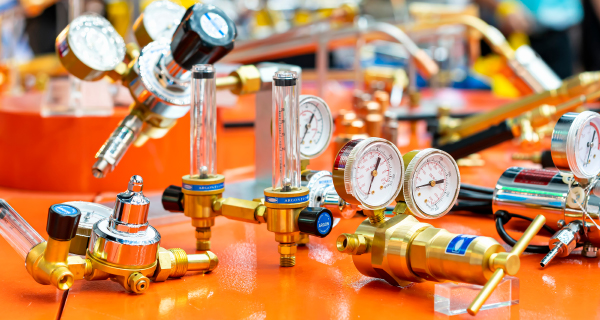
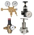
Figure 5: Various types of welding regulators
Regulators designed for specific purposes
- TIG (tungsten inert gas) welding regulators: These welding regulators are found mainly in flowmeter or flow gauge designs with flow reading in liters per minute and cubic feet per hour and with male threading. Argon (100% pure) is used in TIG welding on various materials since this gas promotes the stability of the arc, leaving precise welding and a surface with a shiny appearance. Typically, gas flow rates for TIG welding are set by a flowmeter between 4 lpm and 20 lpm.
- MIG (metal inert gas) welding regulator for argon, helium, and argon/CO2mixtures: This regulator is suitable for joining materials such as carbon steel, mild steel, and stainless steel using Argon / CO2 gas mixtures. An output of 35 liters per minute or higher is ideal for MIG welding. Since turbulent or low flows could contaminate the weld, most welding regulators designed for MIG applications adjust the outlet gas flow to have accurate flow measurements.
- Oxy-fuel welding regulators: In this welding technique, two gasses contained in their respective bottles are used, and so two welding regulators are required to carry out the welding or cutting. These regulators are typically a two-stage regulator type in industrial and high-use applications. This is an acceptable substitution for low-use and volume users to reduce cost. In Oxy-fuel welding and cutting applications, the regulator only adjusts the pressure; the flow rate is adjusted on the torch.
- Fuel gas welding regulators: Acetylene, propane, and propylene are the standard fuels used in welding. Acetylene is highly unstable and explosive at high pressure, so it is usually kept dissolved in a specific material. The regulator for acetylene has an entirely different internal design due to the low-pressure nature of acetylene. Ensure that acetylene and propane regulators are only utilized with the specific gas they are intended for. However, it is possible to use propane regulators for propylene as it contains approximately 50 percent of propane.
- Propane tank regulator: Propane remains a liquid under pressure while stored in the tank, but it becomes a lighter-than-air substance when consumed, building up to extremely high pressure. It is crucial to regulate this pressure as it exits the tank, or it may rupture the connecting hoses or even cause an explosion. Pressure regulators help dispense the liquid in the tank so it can be consumed safely and efficiently. Propane regulators and their connections to the tank are usually made of brass, as brass is resistant to sparks. Aluminum is another option for the pressure regulator’s housing material as it is lightweight and spark-resistant. A propane pressure gauge, also known as a propane tank pressure gauge, is a device used to measure the pressure inside a propane tank. A pressure gauge for propane tank can help determine when the tank needs to be refilled and can also alert the user to any potential issues with the propane system.
Certifications and approvals
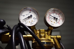
Figure 6: ISO 5171 refers to pressure gauges used in welding, cutting, and allied processes
- The welding regulators must comply with the regulations of the International Organization for Standardization (ISO) 2503 for Gas welding equipment - pressure regulators and pressure regulators with flow-metering devices for gas cylinders used in welding, cutting, and allied processes up to 300 bar (30 MPa). The pressure gauges used on regulators must comply with ISO 5171, a standard for pressure gauges used in welding, cutting, and allied processes.
- According to the German Institute for Standardization, the bottle connection of a welding regulator shall comply with the standard requirements for inlet and outlet bottle valves connections for bottle test pressures up to 300 bar (DIN 477-1) and bottle test pressures from above 300 bar to 450 bar (DIN 477-5).
- Other organizations, such as the Compressed Gas Association (CGA) or British Standard Institution (BS 341), also establish standard measures for bottle valve connection. Some manufacturers use these parameters to fabricate the inlet connection of the bottle of their welding regulators.
Selection criteria
The proper selection of a welding regulator is essential for an adequate gas supply to the welding torch, without leaks and avoiding possible accidents.
- Type of gas: A welding regulator's internal and external design and construction material may vary according to the gas type. Welding regulators are identified with the type of gas for which they are calibrated, and some manufacturers also identify them with colors (for example, red for acetylene regulators).
- Connectors: It is necessary to know the type of gas cylinder connection since the regulators can be male, female, and of different standard sizes. Generally, the inlet gas connection for fuel gasses is a left-hand type and for non-fuel gasses is a right-hand type.
- Design: Use a flowmeter or gauge for flow control applications. Otherwise, use a welding regulator is used to control the outlet pressure.
- Measurement scale: The measurement scale should be within the application range to quickly read the flow or pressure.
- Stability of working pressure: Use single-stage regulators for gasses from low-pressure sources or where a delivery pressure and flow rise (due to cylinder pressure decay) do not affect the work results. Use a dual-stage regulator if the working pressure is challenging to adjust regularly.
- Safety standards: Verify that the welding regulator complies with quality and norm standards to avoid equipment damage and possible accidents.
Applications
- Argon or argon/helium mixture regulators with a flowmeter are used to weld aluminum, copper, or nickel alloys by applying the MIG and laser beam welding technique.
- Steel welding using the MAG and electro-gas technique employs argon /O2 regulators.
- Atomic hydrogen welding uses hydrogen regulators for the rapid welding of alloys such as stainless steel as an alternative to stick welding.
- Argon and hydrogen welding regulators are used for shielding and plasma gas in plasma welding (PAW) to weld titanium and stainless steel pipes. They are also used in the marine and aerospace industries.
FAQs
How does a welding regulator work?
A welding regulator reduces the high-pressure gas from a cylinder and delivers the desired pressure to the welding torch as constantly as possible.
How long do welding regulators last?
If a welding regulator is of high quality, properly installed, operated, and maintained, it will have a prolonged lifespan. As a guideline, the British Compressed gasses Association (BCGA) estimates five years.
How do I know what welding regulator type I have to use?
Use a dual-stage regulator for stable and consistent operation when the working pressure is a critical variable. Use a single-stage regulator for gasses from low-pressure sources.
