


Valve Symbols in Process and Instrumentation Diagrams
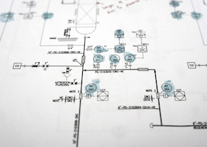
Figure 1: A process and instrumentation diagram
The Process and instrumentation diagram, commonly known as a P&ID, shows the connections between process equipment. The diagram indicates the flow directions, safety and control measures, and pressure ratings of a system through visual symbols. In order to trace faults, isolate equipment and locate items for maintenance, the ability to read P&IDs is essential.
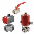
In each process and instrumentation diagram, valves have specific symbols that make them easy to recognize. The symbol typically consists of the actual valve symbol, and the actuation method such as pneumatic, hydraulic, or electric.
Table of contents
- How do I read valve symbols and P&ID diagrams?
- Valve symbols
- Valve states
- Actuator type symbols
- End connections
- Proces lines
- Signal lines
View our online selection of valves!
How do I read valve symbols and P&ID diagrams?
The valve symbols used in a P&ID diagram are standardized and the same globally. This makes it incredibly easy to read a diagram once the user knows what each symbol means.
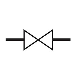
2-way valves
Two-way valves can be recognized by the two triangles that point towards each other, such as the gate valve symbol seen in figure 2. The direction of flow is shown by the arrowhead on the line symbols. Some of the most common 2-way valve symbols are ball valves, butterfly valves, plug valves, gate, valves, etc. Examples of these symbols can be found further down in this article.
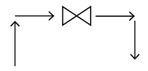
Figure 2: A gate valve with the direction of flow running from left to right.
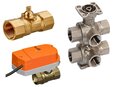
3-way and 4-way valves
Valves with multiple ports such as 3-way and 4-way valves have a broadly similar look where an additional triangle is added to the symbol. These can also have the addition of an L-port or T-port designation. These are shown by the lines within the ball symbol.
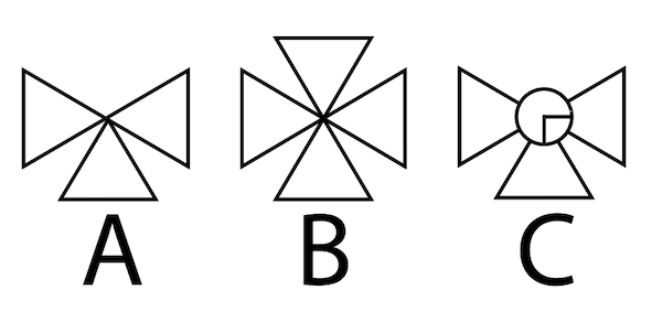
Figure 3: Three-way valve (A), four-way valve (B), three-way valve with L-port connection (C)
Valve states
Valves can be normally open, normally closed, or bistable. Normally open means that the valve is open when not actuated. Normally closed means the valve is closed when not actuated and open when actuated. Bistable means they retain their position during power loss and require a separate action to switch the valve state, an example being a latching solenoid valve. There are several variations to these states, such as valves that are generally normally open, valves that are generally closed, and more.
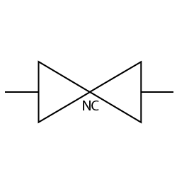
Remember that a blacked-out valve symbol does not necessarily mean that the valve is normally open or normally closed, as these are used interchangeably. Much clearer norm would be to use the letters NC or NO as we have done in the symbol examples.
Actuators
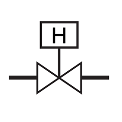
The third meaningful way how a valve can be recognized on a P&ID is the actuator type. The actuator type is shown as a line coming from the center of the valve, with a smaller symbol on top of the line. Electric and hydraulic actuation are shown as letters, as shown in Figure 4.
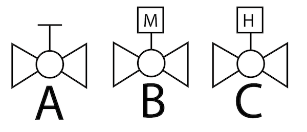
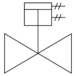
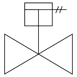
Figure 4: Valve symbols showing a manually operated valve (A), an electrically actuated valve (B), and a hydraulically actuated valve (C).
End Connections, process lines, signal lines, vessels, and equipment
Besides the features of the valves, on a P&ID diagram, a user can find many more symbol types. These include:
- End connections: End connections are the connections between the valve and the process lines. These can be flanged, threaded, weld, or socket weld connections with different lines and circles showing the type of connection. The parallel lines indicate that the valve can be removed without affecting the pipe in a flange connection. A filled-in square represents a permanent welded connection, while an unfilled circle represents a temporary threaded connection. Unfilled squares indicate socket-weld connections.
- Process lines: Process lines include pipes, tubes, and hoses shown in various styles, such as insulated pipes, flexible pipes, cooling, and heating pipes. Each line is labeled with a number, including information about the component's class, size, insulation, etc. Pipes are kept apart in the drawing if they cross but aren't connected by breaking a line or adding a curve.
- Signal lines: Information and signals must be relayed correctly in a system. This can be done through electric, pneumatic, data, sonic, fiberoptic, and other signal types.
- Equipment: This includes everything from vessels such as storage tanks and drums to steam vessels, mixing vessels, gas bottles, and more. Pumps, fans & compressors represent blowers, fume exhausters, air compressors, and pressure fans. Sensors, transmitters & meters are an essential part of the process diagram. The flow process is monitored, recorded, and controlled by sensors, transmitters, and meters. Due to the massive number of symbols involved in this category and this article being focused on valves, they are not included.
- Tag numbers: Letters and numbers are typically included in the P&ID diagram. These indicate the properties of the media being measured and its function.
Valve symbols
| Symbol | Type | Usage |
 |
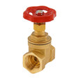
Gate valve | A gate valve is a control valve that allows media to flow through unobstructed or stops the fluid flow. One advantage of a gate valve is the straight-through unobstructed passageway. |
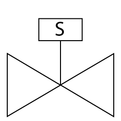 |
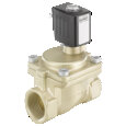
Solenoid valve | A solenoid valve is a valve that is electromechanically controlled. It is typically used for gases and clean media. |
 |
Relief valve | A relief valve, also known as a pressure relief valve, is a device that lowers the pressure to prevent damage to the system. Their function is to protect pressure-sensitive equipment from damage caused by overpressure. |
 |
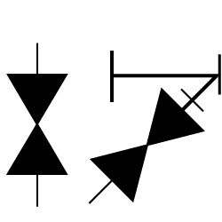
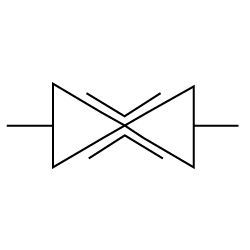
Safety valve | Safety valves are seen as a last resort safety measure. They are found in power plants, petrochemical systems, boilers, etc. Safety valves are fail-safe devices that automatically stop the increase of overpressure beyond a determined limit. |
 |
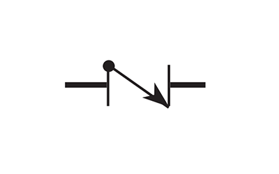
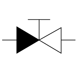
Check-stop valve | A Stop Check Valve combines a check valve and a globe valve. They prevent the reversal of flow in a piping system. |
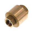
 |
Check valve | A check valve is a device that only allows the flow of fluids in one direction. They only enable media flow in one direction and are commonly referred to as ‘one way valves’ or ‘non-return valves.’ |
 |
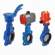
Butterfly valve | Butterfly valves work similar to ball valves. The butterfly is a disk connected to a rod. It closes when the rod rotates the disc by a quarter turn to a position perpendicular to the flow direction. |
 |
Plug valve | A plug valve uses a cylindrical or tapered plug to permit or prevent straight-through flow through the body. |
 |
Diaphragm valve | Diaphragm valves control the flow of liquids and gases. They have a rubber diaphragm that moves up and down within the valve's body, causing opening and closing against a hard seat. |
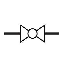 |
Ball valve | A ball valve is a shut-off valve that controls the flow of a liquid or gas utilizing a rotary ball with a bore. |
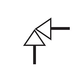 |
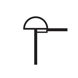
Angle valve | An angle valve has an inlet and an outlet port perpendicular to each other and is used to prevent or control the flow of a liquid in a pipe. |
 |
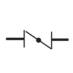
Bleed valve | A bleed valve is a valve for running off a liquid from a tank or tube or allowing accumulations of gas in a liquid to blow off. |
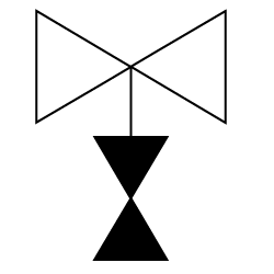 |
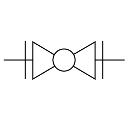
Block and bleed valve | A block and bleed valve isolates or blocks the flow of fluid in a system, so the fluid from upstream does not reach other components of the system that are downstream. This can be a single block and bleed valve or a double block and bleed valve used for stricter isolation of process fluid. |
 |
Piston-operated valve | A piston valve is used to control the motion of a fluid along a tube or pipe by the linear movement of a piston within a chamber or cylinder. |
 |
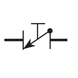
Float-operated valve | Float valves control liquid levels mechanically. As the liquid's surface rises or falls, a float detects the elevation change and opens or closes the valve accordingly. A float switch uses a similar process. |
 |
Knife valve | For thick liquids and dry bulk solids, knife gate valves are used. It consists of just one piece of metal, usually pointed like a knife. |
 |
Slide valve | In a slide gate valve, the gate and the seat are parallel. Slide gate valves utilize line pressure and positioning to achieve a tight seal. |
 |
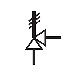
Needle valve | Fluids and gases can be controlled accurately with needle valves. Adjustments are gradual and smooth so that flow rate can be controlled, but they can also be used as shut-off valves. |
 |
Pinch valve | Two-way pinch valves are used to shut off or control the flow of corrosive, abrasive, and granular media. The valves are operated by compressed air pressure. |
Valve states
| Symbol | Type | Usage |
 |
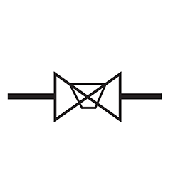
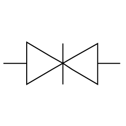
Special valve | A special-purpose valve is a valve that can do certain functions more than the two-way isolation, control, and check. So this type of valve is considered a special purpose valve. |
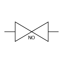 |
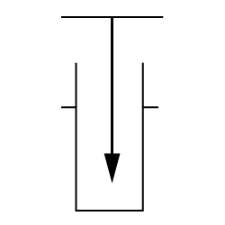
Normally open valve | Normally open valves are always open. They close when actuated and open again when not actuated. |
 |
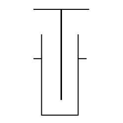
Normally closed valve | Normally closed valves are always closed. They open when actuated and close again when not actuated. |
Actuator type symbols
| Symbol | Type | Usage |
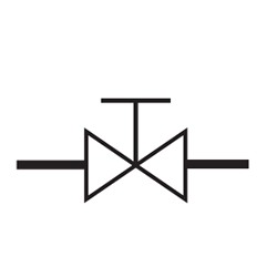 |
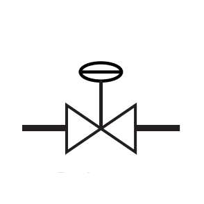
Hand Operated (Manual) | Manually-operated valves offer a reliable and durable system for opening and closing flow when the system has to be switched frequently and does not require much force to actuate. |
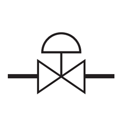 |
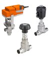
Pneumatic (Diaphragm) | The vast majority of diaphragm valves are operated by pneumatic actuators; in this case, air pressure is applied through a pilot valve to the actuator, which raises the diaphragm and opens the valve. |
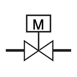 |
Motor (Electric) | Motor-actuated valves are actuated by electric motors. Different types of motor-actuated valves are defined based on how those valves are actually opened or closed and what applications they are used for. |
 |
Hydraulic | For valves that require large amounts of force, hydraulic actuators are typically used. Hydraulic actuators of the piston type are the most common. |
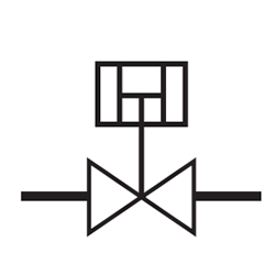 |
Pneumatic (Rotary Piston) | Using compressed air, a pneumatic rotary actuator generates its operating energy. They are often used to remotely control valves. |
 |
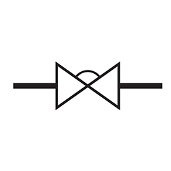
Balance Diaphragm | A pneumatic diaphragm balance valve, controls upstream vs downstream pressure via communication of the process fluid above and below the balancing diaphragm. |
End connections
| Symbol | Type | Usage |
 |
Flange connection | Flanged connections are the most common method of connecting valves, regardless of the pressure level and valve size. |
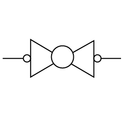 |
Threaded connection | Pipes and valves connected through threaded connections are compact and streamlined. Valve end connections are typically female threaded, into which a male threaded pipe fits. Also available are valves with male threaded connections, as well as valves with one female end and one male end. It is necessary for threaded connections to meet various standards. |
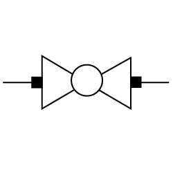 |
Weld connection | An equal-diameter valve and pipe are used to make a welded connection. They are chamfered on the outer edges for welding material to fill in the valley. They are welded around the rims. In general, butt welds are reserved for smaller sizes, usually under 2". |
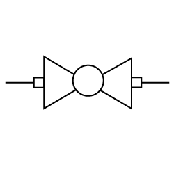 |
Socket weld connection | Compared to the pipe's outer diameter, the valve socket has an inner diameter that is slightly larger. The pipe is placed in the socket and welded around the rim. |
Process lines
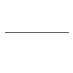 |
Standard pipe | This symbol is used for all standard pipes and tubes in a P&ID diagram. If the line is printed bold it signifies a major line, if not it is designated a minor line |
 |
Insulated pipe | Insulated pipes, such as used for steam. The insulation is shown only on lines that are to be insulated. A symbol and code letter shall designate insulation. |
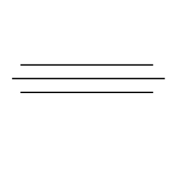 |
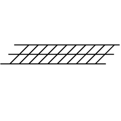
Jacketed pipe | Process piping systems designed to convey viscous fluids can benefit from jacketed piping and tubing. The outer pipe jacket may contain a heated liquid that warms the fluid flowing through the product pipe, making it easier to pump through the process lines. |
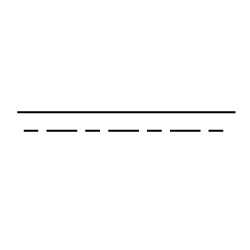 |
Cooling or heating pipe | Pipes used to transport hot or cold media. |
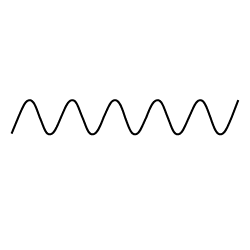 |
Flexible pipe | To distinguish solid piping from flexible tubes, pipes, and hoses, the flexible pipe symbol is used. |
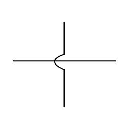 |
Pipes cross but are not connected. | If a P&ID diagram has pipes that cross in the drawing, but are not physically connected this symbol is used. |
Signal lines
| Symbol | Type | Usage |
 |
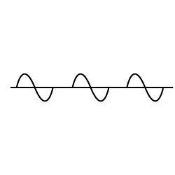
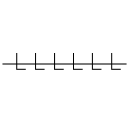
Pneumatic signal | A valve is generally controlled by using pneumatic signals. For example, a control valve releases air into the system increasing pressure, which activates a valve at the end of the line. |
 |
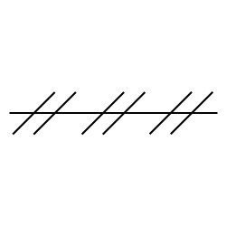
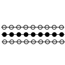
Guided electromagnetic, sonic, or fiberoptic signal. | Typically used in very sensitive environments, guided in this case means through a cable or other means of transporting the signal. |
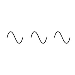 |
unguided electromagnetic, sonic, or fiberoptic signal. | Unguided signals can be unguided electromagnetic signals, light, radiation, radio, sound, wireless, etc. But also A wireless instrumentation signal or wireless communication link. |
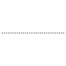 |
Electric or electronic signal | This symbol can be an electronic or electrical continuously variable or binary signal or a functional diagram binary signal. A binary signal is a voltage or current which carries information by varying between two possible values, corresponding to 0 and 1 in the binary system. |
 |
Hydraulic signal | |
 |
Various data communication signals. |
