How To Prevent O-ring Damage
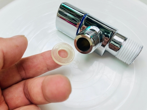
Figure 1: An o-ring for a faucet
Gaskets and o-rings can encounter issues that compromise their functionality; failures in these sealing components can lead to leaks, contamination, and equipment breakdowns. Proper material selection, installation procedures, and regular maintenance are key to preventing failures and ensuring optimal performance. This article explores the most common causes of o-ring and gasket failure, providing insights and solutions to prevent these issues. Understanding the cause of o-ring failure is crucial for effective prevention.
View our online selection of o-rings!
Causes of leaks in o-rings
There are three main reasons why o-rings leak.
- Size: If the seal is too big, the excess material will bunch up in the groove, causing excessive compression and resulting in an uneven surface. Conversely, if the ring is too small, it will be overstretched, preventing the material from forming a proper, leak-free seal.
- Installation: O-rings allow for some stretching, and in fact, need some stretching to fit snugly. Incorrect installation will cause the internal and external dimensions to change. Stretch should be between 1%-5%, with 2% as the ideal in most applications to provide an effective seal. A stretch greater than 5% is not recommended. The resulting stress will cause accelerated aging and cross-section reduction, ultimately leading to leaks. An exception from this rule is a floating seal. A floating seal is an o-ring that sits freely in a groove. These are used where some leakage is permitted as well as when reduced friction is needed. Read our article on the o-ring installation to learn more.
- Material: Using the wrong material for the system temperature, chemical, or pressure will cause damage to the o-ring and cause the seal to fail. Look at the various material choices available in our seal material guide, which covers many of the components used in o-rings, to learn more about material choices. To find out if an o-ring is compatible chemically use our chemical resistance chart.
Troubleshooting o-ring damage
Table 1: O-ring failure analysis
| Failure mode | Visual indication | Cause | Solution |
Compression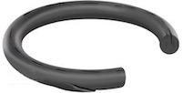 |
Circumferential splits on compressed surface, permanent deformation (compression set) | Extreme pressure levels, incorrect groove dimensions | Choose materials with better compression set or higher pressure resistance; check groove dimensions. |
Rapid pressure changes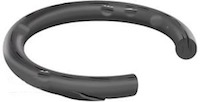 |
Blisters, pockmarks, pits, complete rupture | Rapid decompression causing gas expansion | Gradually reduce system pressure; use materials designed to resist explosive decompression (e.g., NORSOK M710 standard). |
Installation damage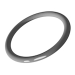 |
Cuts, nicks, twisting, gashes | Skiving with metal parts, improper lubrication, incorrect sizing, careless installation | Use correct tools, protect sharp edges, ensure proper lubrication, verify correct o-ring sizing. |
Excessive friction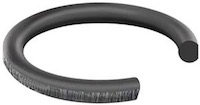 |
Grazed surface, deeper lacerations, breaking | Repeated contact between o-ring and housing, insufficient lubrication, rough metal surfaces, abrasive contaminants | Ensure correct lubrication, use materials with improved abrasion resistance (e.g., polyurethane, PTFE, NBR), reduce contaminant ingress with wiper or scraper rings. |
Chemical attack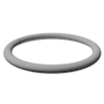 |
Blisters, cracking, changes in hardness, discoloration | Reaction between elastomer and aggressive chemicals (acids, bases, solvents, oils) | Select elastomer materials compatible with the application media. |
Chemical swell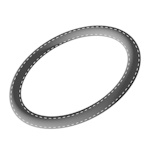 |
O-ring appears larger than original dimensions | Elastomer absorbs surrounding media due to chemical similarity | Switch to an elastomer material with proven resistance to the chemical environment. |
Out-gassing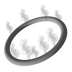 |
The release of trapped gasses or volatile compounds from the o-ring material with usually no visible change, shrinkage in extreme cases | Volatilization of constituent ingredients under vacuum conditions | Use materials formulated with pure polymers and no volatile ingredients; select materials rated for the correct temperature. |
Thermal degradation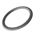 |
Radial cracking, shinier surfaces, frilly edges, nibbling on low-pressure side | Exceeding maximum temperature ceiling, excessive temperature cycling | Select higher temperature elastomer materials (e.g., FFKM, fluorosilicone, HNBR), optimize groove/gland design. |
UV degradation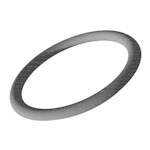 |
Discoloration, cracking, disintegration on exposed surfaces | Ultraviolet light causing fragmentation of polymer chains | Use black materials and fluorinated materials for higher UV resistance. |
High-pressure extrusion 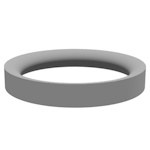 |
Nibbled, chipped, or frilly edges on low-pressure side | High pressures forcing material into clearance gaps, pressure pulses | Use harder seal materials and backup devices to reduce clearance gaps; ensure correct sizing of o-rings and backup devices. |
Plasma attack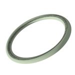 |
Even material loss on surface in contact with plasma, powdery residue, discoloration | High-energy ionized gasses and radicals attacking the material's organic structure | Use materials with high plasma resistance (e.g., perfluoroelastomers, polyimide). |
Flattened surfaces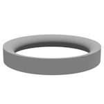 |
Flattened surfaces on o-ring cross-section, unable to recover to original shape | Physical and chemical changes at elevated temperatures, improper gland design, volume swell | Select elastomer materials with low compression set and higher temperature capability (e.g., FKM, silicone, EPDM); ensure proper gland design; follow industry standards (e.g., AS568); use more flexible polymer structures. |
FAQs
What causes o-ring failure?
O-ring failure can be caused by improper installation, chemical degradation, excessive temperature, pressure, or wear and tear.
What will a bad o-ring cause?
A bad o-ring can lead to leaks, loss of pressure, and system failure.
What are common visual signs of flange gasket failure?
Common signs include leaks, visible damage like cracks or tears, and deformation or misalignment of the gasket.


