Pressure Transducer Troubleshooting

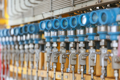
Figure 1: Pressure transducers encounter issues that compromise their accuracy in industrial systems
Troubleshooting pressure transducers is critical in maintaining the reliability and accuracy of industrial systems. Pressure transducers can encounter several issues that affect their performance. Understanding common problems, their causes, and effective troubleshooting methods is essential for minimizing downtime and ensuring precise pressure measurements. This article discusses typical pressure transducer problems and offers insights on how to address them.
View our online selection of pressure transducers!
Common pressure transducer problems and how to solve them
Installation issues
Installation issues in pressure transducers arise from incorrect or improper mounting, wiring, or connection to the system.
Solution
- Mechanical connection: Ensure the process connection is secure. Most transducers use BSP or NPT threads. Verify that the fitting mates properly with the pressure port or use the correct adaptor. After installation, inspect the connection for any leaks that could lead to signal loss.
- Electrical connection: Depending on whether the transducer outputs millivolts, volts, or current, ensure that the wiring matches the specified configuration in the transducer's manual.
Electrical interference
Transducers are sensitive to electrical interference from nearby unshielded cables, power lines, and other electrical equipment, which can affect calibration and signal accuracy.
Solution
- Shielding: Install proper electrical shielding to protect the transducer from electromagnetic interference (EMI) and radio-frequency interference (RFI). Also, avoid multiple grounding points to prevent ground loops.
- Placement: Position transducers away from potential sources of interference, such as high-voltage lines and heavy machinery.
Calibration drift
Excessive drift in calibration settings can indicate that the transducer is not suitable for the application or is affected by environmental factors.
Solution
- Annual calibration: Regularly check and recalibrate the transducer, ideally on an annual basis.
- Signal conditioning: Use transducers with built-in signal conditioning to mitigate the effects of electromagnetic fields and electrical noise.
Pressure spikes
Sudden or rapid pressure changes, such as water hammer or pressure impulses, can damage the transducer.
Solution
- Snubbers: Install snubbers directly in the pressure line, close to the transducer to protect the transducer from pressure spikes. Note, snubbers may slow down the measurement response time.
- Pressure relief valves: Install a pressure relief valve upstream of the transducer to release excess pressure and prevent spikes, ensuring the transducer operates within safe limits.
Environmental factors
Environmental conditions like moisture, extreme temperatures, and vibration can degrade the performance of pressure transducers.
Solution
- Material selection: Use transducers made from robust materials like stainless steel to withstand harsh conditions.
- Environmental protection: Implement measures to protect the transducer from moisture, temperature extremes, and mechanical vibrations.
Wiring and power supply issues
Damaged wiring, short circuits, inadequate power supply, and reverse polarity can lead to transducer failure.
Solution
- Regular inspection: Routinely inspect wiring and connections for damage or wear.
- Correct polarity: Ensure correct polarity and adequate power supply as per the transducer's specifications.
Table 1 outlines common symptoms, potential causes, and recommended solutions for issues related to pressure transducers. It serves as a quick reference guide for diagnosing and addressing problems to ensure optimal performance and reliability of the equipment.
Table 1: Troubleshooting a bad pressure transducer
| Symptom | Cause | Solution |
| Visible leaks around the pressure port | Damaged seals or improper installation | Inspect and replace seals, ensure proper installation |
| Gradual degradation in the output signal over time | Calibration drift or environmental factors | Regular recalibration, protect from environmental conditions |
| Abrupt changes in the signal | Electrical interference or pressure spikes | Improve shielding, install snubbers or PRVs |
| Total loss of signal | Wiring issues, power supply failure, or transducer damage | Inspect and repair wiring, check power supply, replace the transducer if necessary |
| Output remains constant regardless of pressure changes | Sensor element failure or blockage in the pressure port | Inspect and clean the pressure port, replace the sensor element |
| Inconsistent or inaccurate readings | Electrical interference, environmental factors, or calibration issues | Improve shielding, protect from environmental conditions, recalibrate the transducer |
Table 2: Testing procedures for different types of pressure transducers
| Transducer type | Connections | Expected output |
| 2-wire current pressure sensor |
|
Current range from 4 to 20mA in no-load conditions. |
| 3-wire current pressure sensor |
|
Current range from 4 to 20mA in no-load conditions. |
| 3-wire voltage pressure transducer |
|
Voltage that matches the manufacturer’s datasheet in no-load conditions. |
| 4-wire voltage pressure transducer |
|
Voltage equal to the no-load voltage specified in the datasheet. |
Read our pressure transducer testing article for more information on how to use a multimeter to check for a faulty transducer.
FAQs
What causes transducer failure?
Transducer failure can be caused by electrical overload, physical damage, environmental factors (e.g., extreme temperatures, moisture), corrosion, improper installation, or manufacturing defects.
What are the signs of a bad transducer?
Signs of a bad transducer include erratic or no output signal, inaccurate readings, drift in measurements, physical damage, and failure to respond to pressure changes.
How can I troubleshoot a 4-20 mA pressure transducer that is not responding to pressure changes?
Check the power supply, verify the wiring, inspect for physical damage, and compare the transducer's output to a known-good unit.


