


Check Valves In Hydraulic Systems
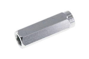
Figure 1: Inline steel check valve for hydraulic systems
A hydraulic check valve allows fluid flow in a single direction and protects important hydraulic system components. When properly installed, a hydraulic check valve can stop potentially contaminated fluid from mixing with the fluid reservoir, keep the system primed, and relieve pressure. This article will examine check valves' integral role in hydraulic systems.
Table of contents
- Hydraulic check valve purpose
- Operating principle
- Types of hydraulic check valves
- Check valves in hydraulic applications
- Hydraulic check valve symbols
- Challenges & best practices
- FAQs
View our online selection of check valves!

Hydraulic check valve purpose
Check valves are used in hydraulics to prevent fluid from returning to the pump that suctions it from the reservoir. Other essential functions of a check valve in hydraulic systems are:
- Block pressure spikes: Directional control valves in hydraulic systems can close to block flow. This deadheads the pump, meaning the pump is operating but is unable to move fluid. Pressure rapidly increases in the system, and the hydraulic check valve operation stops the pressurized fluid from returning to the pump and damaging it.
- Keeping prime: The inside of a pump needs to have fluid for the pump to operate without risking damage. A check valve keeps fluid from flowing out of the pump when the system is off.
- Prevent backspin: A hydraulic accumulator is a component that some hydraulic systems use. It keeps the fluid pressurized while the system is off. Check valves prevent the pressurized fluid from returning to the pump and causing backspin.
- Protecting multiple pumps: A typical hydraulic system has two pumps. Check valves at the discharge points of each pump prevents the operating pump from moving fluid into the pump that is not operating.
Note: The flow direction of a hydraulic check valve is important, and incorrect check valve installation can lead to failure, which can cause system inefficiencies and potentially damage hydraulic components.
Operating principle
The operating principle of a hydraulic check valve is based on the differential pressure across the valve. Figure 2 is a hydraulic check valve diagram that illustrates this. A valve with a spring has a cracking pressure. This is the pressure required at the inlet to overcome the spring force and open the valve (Figure 2 top). The valve's movable internal component, such as a ball, piston, or disc, is pushed away from the valve seat by the fluid pressure. Conversely, if the pressure on the outlet side becomes greater than the pressure on the inlet side, the internal component is forced back onto the valve seat by the spring, sealing the valve and preventing reverse flow (Figure 2 bottom).
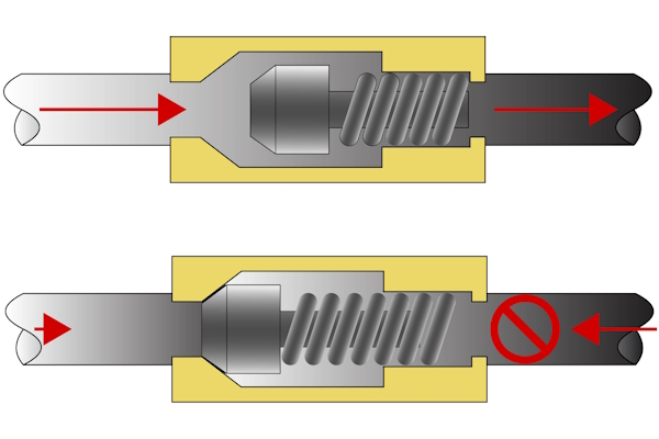
Figure 2: When inlet pressure overcomes the check valve's cracking pressure, the valve opens. When inlet pressure drops below the cracking pressure or the downstream pressure rises, the valve closes.
Types of hydraulic check valves
Various types of check valves are suitable for hydraulic systems. The different types of valves are constructed of different materials, have different connection types, and operate up to different max pressures.
Materials
Hydraulic systems demand valves suitable for high pressures, so common materials used to construct these valves are steel and stainless steel. Read our chemical resistance guide to learn more about how the following materials work with different types of media.
Steel hydraulic check valve
- Max operating pressure (bar): 100, 160, 250, 300, 350, 400, depending on the valve
- Minimum operating pressure: 0.2 bar up to 8 bar, depending on the valve
- Seal material: Steel, NBR if the valve has cutting ring connections
- Temperature range: -20 °C to 200 °C (-4 °F to 392 °F)
-
Connection types:
- Inner thread cylindrical BSPP-G
- Cutting ring
- Cutting ring and outer thread cylindrical BSPP-G
Stainless steel hydraulic check valve
- Max operating pressure (bar): 100, 160, 250, 300, 340, or 400 bar, depending on the valve
- Minimum operating pressure: 0.2 bar up to 1 bar, depending on the valve
- Seal material: FKM
- Temperature range: -25 °C to 200 °C (-13 °F to 392 °F)
-
Connection types:
- Inner thread cylindrical BSPP-G
- Compression ring
- Cutting ring
- Compression ring and outer thread cylindrical BSPP-G
- Cutting ring and outer thread cylindrical BSPP-G
Check valves in hydraulic applications
Hydraulic check valves are essential components used across various industries to ensure proper fluid flow and maintain pressure, preventing backflow that could damage systems. Here are some key applications:
- Industrial machinery: Used in hydraulic presses and injection molding machines for consistent operation. They maintain pressure in systems like conveyor belts and robotic arms.
- Automotive industry: Integral to anti-lock braking systems (ABS) for reliable braking. They maintain pressure for smooth steering control in power steering systems.
- Aerospace: Ensure correct fluid flow for safe gear extension and retraction in landing gear systems. They maintain pressure in lines controlling critical flight components.
- Construction and heavy equipment: Control hydraulic cylinders for precise movement in excavators and loaders. They prevent uncontrolled movements by maintaining lifting mechanism pressure in cranes.
- Marine applications: Ensure smooth operation in steering systems and stabilizers. They maintain pressure for reliable cargo handling in winches and lifts.
- Agricultural machinery: Control implements and attachments for efficient farming in tractors and harvesters. They maintain pressure for consistent water flow in irrigation systems.
- Renewable energy: Ensure correct blade adjustment in hydraulic pitch control systems in wind turbines. They control water flow for efficient energy generation in hydroelectric plants.
Hydraulic check valve symbols
Figure 3 shows P&ID schematic symbols for hydraulic check valves: check valve with a spring (Figure 3 labeled A) and check valve without a spring (Figure 3 labeled B)
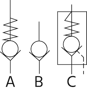
Figure 3: Hydraulic check valve P&ID schematic symbols: check valve with a spring (A) and check valve without a spring (B).
Challenges & best practices
-
Incorrect installation: Improper installation of hydraulic check valves can lead to inefficiencies and damage.
- Solution: Ensure valves are installed in the correct orientation, following flow direction markings to prevent backflow and maintain system efficiency.
-
Material compatibility: Using the wrong material for check valves can cause premature wear or failure.
- Solution: Select valves made from materials compatible with the hydraulic fluid and capable of withstanding high pressure and temperature, such as steel or stainless steel.
-
Pressure variations: Substantial pressure fluctuations can cause valve failure if not properly addressed.
- Solution: Choose a check valve with an appropriate cracking pressure to ensure it operates correctly under varying system pressures.
-
Contamination: Contaminants in hydraulic fluid can obstruct valves, causing malfunction.
- Solution: Implement regular maintenance to inspect and clean valves, preventing contamination and ensuring proper function.
-
Maintenance neglect: Lack of regular maintenance leads to valve degradation and system compromise.
- Solution: Establish a maintenance schedule to routinely check and service check valves, maintaining their effectiveness.
-
System monitoring: Without monitoring, issues like pressure spikes may go undetected.
- Solution: Use pressure gauges and flow meters to monitor system performance, enabling early detection and intervention for issues.
-
Training and documentation: Inadequate training can result in improper installation and maintenance.
- Solution: Provide thorough training and clear documentation for personnel responsible for hydraulic systems, ensuring proper installation and maintenance practices.
FAQs
What does a hydraulic check valve do?
The use of a check valve in a hydraulic system is to allow pressurized fluid in a hydraulic system to flow in only one direction. This protects the system’s pump(s) and prevents contamination.
How does a hydraulic check valve work?
When the system’s pressure overcomes the check valve’s cracking pressure, the valve opens to relieve pressure in the system and protect valuable components.

