


Circuit Breaker Installation
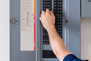
Figure 1: Circuit breaker panel showing the main panel (bottom), subpanels (top), and labels (left)
Circuit breakers protect electrical circuits from overloading, short circuits, and other electrical hazards. Proper installation of circuit breakers is vital to ensure the safety and reliability of electrical systems. This article discusses how to install a new circuit breaker in an electrical panel, from selecting the right breaker to wiring it correctly and safely. Read our circuit breaker overview article for a complete guide on circuit breaker working and types.
Note: Take proper precautions when installing circuit breakers, including following all safety guidelines and using the correct equipment and techniques. This article is for informational purposes only and should not be used as a substitute for professional advice or guidance.
Table of contents
- Choose the right circuit breaker
- Turn off the power
- Remove the panel cover
- Install the circuit breaker
- Test the circuit breaker
- Replace the panel cover
- Circuit breaker labels
- Circuit breaker lockout
- FAQs
View our online selection of circuit breakers!
1) Choose the right circuit breaker
The first step in installing a circuit breaker is to choose the right breaker for the electrical system. Circuit breakers come in different sizes, types, and amperages. Hence, selecting one that matches the voltage and amperage of the electrical system and the load it will be carrying is essential.
- Determine the amperage and voltage of the system. This information can be found on the main electrical panel or in the electrical specifications of the appliances and devices.
- Once the amperage and voltage of the system are determined, calculate the maximum amperage of the circuit breaker. Add up the amperage ratings of all the devices and appliances connected to the circuit, and then add a safety margin of 20% to ensure that the circuit does not overload. For example, to install a circuit breaker for a room with 20 amps of electrical load, choose a breaker with a rating of at least 24 amps (20 amps + 20% = 24 amps).
- For most residential electrical circuits, 15-amp breakers are used for lighting circuits, receptacle circuits in bedrooms, and other low-power circuits. These circuits typically carry a maximum load of 1,800 watts (15 amps x 120 volts = 1,800 watts), which is sufficient for most lighting and plug-in devices like televisions, computers, and small kitchen appliances. On the other hand, 20-amp breakers are used for circuits that power larger appliances, like refrigerators, air conditioners, and power tools, as well as for kitchen countertop receptacle circuits, bathroom receptacle circuits, and other circuits where heavier loads are expected. These circuits typically carry a maximum load of 2,400 watts (20 amps x 120 volts = 2,400 watts).
Note: The voltage and frequency of the main power supply vary from one country to the other. Countries like the USA use the main power supply of 120 volts operating at 60 Hz, whereas those in Europe like the UK, Netherlands, and Germany operate at 230 volts and 50 Hz. See the complete list of countries with their corresponding mains power supply voltage and operating frequencies for more details.
- In a standard North American residential electrical system, there are two 120-volt 'hot' wires coming from the utility company that supplies power to the home's electrical panel. These two hot wires are connected to the panel's main breaker. For 120-volt circuits, each hot wire is connected to a separate 120-volt circuit breaker, and the voltage between the hot wire and neutral wire is 120 volts. For 240-volt circuits, the two hot wires are connected to a double-pole 240-volt circuit breaker. The voltage between the two hot wires is 240 volts, while the voltage between each hot wire and the neutral wire is 120 volts. The appliance, like a dryer or oven, is designed to use 240 volts across the two hot wires to power its heating elements and motor.
- While larger circuit breakers can handle higher loads, the wires and electrical devices connected to the circuit must be able to handle the increased current as well. Installing a larger circuit breaker without ensuring that the wiring and devices can handle the load can create a serious fire hazard.
- Select the appropriate type of breaker. Several circuit breakers are available, each designed for specific applications and environments.
- Standard circuit breakers: Standard circuit breakers are simple circuit breakers that trip when a circuit overloads. They are commonly used in residential and commercial electrical systems. They can be single-pole or double-pole.
- Ground Fault Circuit Interrupter (GFCI) breakers: Ground fault circuit interrupter outlets are installed in areas prone to moisture, such as kitchens, bathrooms, and damp industrial settings.
- Arc Fault Circuit Interrupter (AFCI) breakers: Arc fault circuit interrupters detect arc faults, which are electrical discharges through the air from an electrical component to a grounded component. These not only put people at risk and can lead to electrical and fire damage to property.
Read our article on identifying circuit breaker type for more information on each type of circuit breaker.
2) Turn off the power
The circuit breaker panel, also known as an electrical panel or breaker box, typically looks like a metal box mounted on a wall in a utility room, basement, or garage. The panel usually has a hinged door protecting the circuit breakers inside.
Before installing a circuit breaker, turn off the power to the electrical panel and the circuit breaker being worked on. For this, switch off the main power switch or the main circuit breaker that supplies power to the panel. The main breaker receives power from the utility company and diverts it to individual circuits that power different household devices, like lights, appliances, and outlets. If the main breaker is on the circuit panel, it is usually situated at the top or bottom of the panel (Figure 2). It is likely positioned next to the electricity meters if it is not on the circuit panel.
Afterward, test the breaker with a multimeter to ensure no live current runs through it. Never attempt to work on an electrical circuit while it is still live, as this can result in electrical shocks or burns.
3) Remove the panel cover
Typically, the panel door is hinged on one side and secured with a latch or lock on the other side. In some cases, the panel cover needs to be removed by unscrewing the screws or clips that hold it in place. Ensure not to touch any wires or terminals inside the panel, as they can still carry a residual electrical charge. Use a flashlight to inspect the wiring and locate where to install the circuit breaker by identifying blank areas.
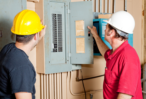
Figure 2: Electricians opening electrical panel door
4) Install the circuit breaker
First, remove one of the knockouts (the small, perforated sections on the enclosure or box that allow for the installation of electrical conduit or wiring) on the panel cover to install the circuit breaker and insert the breaker into the panel box. The breaker should snap into place and securely attach to the bus bar. Once it is installed, wire the circuit breaker by connecting the wires to the terminals using a screwdriver or pliers. The circuit breaker wiring connects the black or red wire to the breaker's hot terminal, the white wire to the neutral bus bar, and the green or bare wire to the ground bus bar. Tighten the screws firmly but not too tight, as this can damage the wires or the terminals.
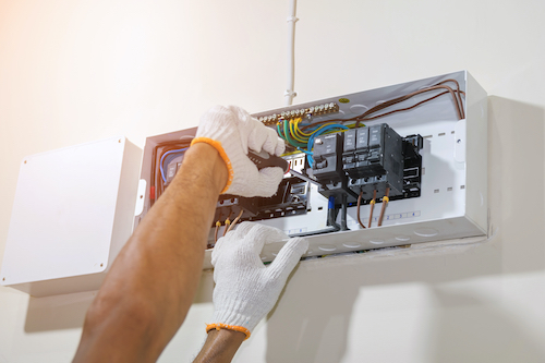
Figure 3: Using a screwdriver to tighten the circuit breaker
5) Test the circuit breaker
After the circuit breaker is installed and wired, test it to ensure it works properly and safely. For this, turn on the power to the panel and the circuit, and test the voltage with a multimeter. The voltage of a specific circuit will depend on the electrical load and the system's design. For example, a typical residential electrical system in the United States operates at 120 volts AC, while a commercial or industrial system may operate at 240 volts or higher. If the voltage is correct, test the circuit by plugging in a device or turning on a light connected to the circuit. If the device works and the breaker does not trip, the circuit is safe and ready to use. If the device does not work or the breaker trips, there may be a wiring problem or a faulty breaker that needs to be checked by a licensed electrician.
6) Replace the panel cover
Once the circuit breaker is installed and tested, replace the panel cover by snapping it back into place or screwing it in with the screws or clips. Ensure the cover is flush and tight against the panel and no wires or terminals are sticking out or touching the cover. Turn on the power to the panel and the circuit, and check if the circuit is working properly and safely. Read our article on how to replace a circuit breaker for more details.
Circuit breaker labels
Look for the panel's circuit directory inside the panel door. Identify the circuit breaker location and record a detailed description of the circuit, such as the load type (e.g., 'refrigerator') or location (e.g., 'living room'), in the designated space. Remember to update the directory accordingly in case any circuits were relocated during the installation process of the new circuit. Read our article on reading circuit breaker panels for more details.
Circuit breaker lockout
A circuit breaker lockout is a safety device used to prevent accidental or unauthorized operation of a circuit breaker. The circuit breaker is locked physically in the "off" position using a lockout device or mechanism.
The lockout device typically fits over the circuit breaker's operating handle, preventing it from being turned on or off. This ensures that the circuit breaker cannot be inadvertently turned on, which could cause electric shock, fire, or damage to the electrical system. Lockout devices may be required by safety regulations and are commonly used in industrial, commercial, and residential settings.
Circuit breaker lockouts are typically used during maintenance or repair work when workers need to de-energize the electrical system to perform tasks safely. Lockout devices may also be used to prevent unauthorized individuals from accessing or operating the electrical system.
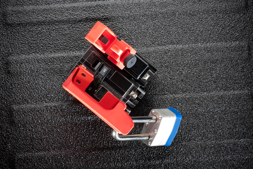
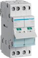
Figure 4: Circuit breaker switch lockout devices attached to a single pole and multipole switches.
Read our articles on miniature circuit breakers, residual current circuit breaker,smart circuit breakers and earth leakage circuit breakers for more details on the features of various circuit breaker types.
FAQs
Where can I install a circuit breaker?
Circuit breakers are typically installed in an electrical panel or a breaker box that is usually located in a utility room, basement, or garage and should be easily accessible in case of emergency or maintenance.
Where is the main breaker located?
The main breaker in a residential electrical system is typically located in the electrical panel or breaker box. It's usually located at the top or bottom of the panel and is labeled with the amperage rating.
