


A Comprehensive Gate Valve Guide
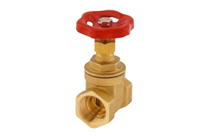
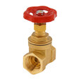
Figure 1: Gate valve
A gate valve controls fluid flow by fully opening or closing the flow path by moving a gate up and down perpendicular to the flow path. This valve has a straight, unobstructed path, minimizing pressure loss and allowing simple cleaning. While slower than quarter-turn valves (e.g., ball and butterfly valves), gate valves are ideal for applications requiring infrequent operation.
Table of contents
- Gate valve diagram
- Gate valve symbol
- Operation
- Advantages
- Comparing other valve types
- Brass gate valves
- Applications
- Selection criteria
- Installing a threaded gate valve
- Maintaining a gate valve
- FAQs
View our online selection of gate valves!
Gate valve diagram
As seen in Figure 2, a gate valve has seven main parts:
- handwheel (A)
- stem (B)
- gasket (C)
- bonnet (D)
- valve body (E)
- flange (F)
- gate (G)
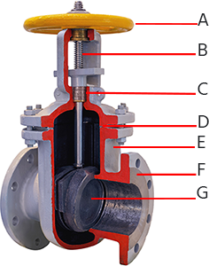
Figure 2: Gate valve parts: handwheel (A), stem (B), gasket (C), bonnet (D), valve body (E), flange (F), and gate (G).
Operation
A gate valve, also known as a sluice valve, operates similarly to other valves. To open the valve, turn the handwheel (Figure 2 labeled A), which moves the gate (Figure 2 labeled G) up or down on the stem (Figure 2 labeled B) via the threads. This valve requires more than one 360° turn of the handwheel to open or close the valve fully. When the gate is lifted, it opens the inlet to the outlet, allowing an unobstructed passageway for the media to flow. When the gate is lowered, it closes and blocks the media flow.
A gate valve should only be used for on/off control. The relationship between the gate's vertical travel and the flow rate is nonlinear, with the greatest changes near complete closure. The relatively high velocity of the flow at partial opening results in gate and seat wear. This, along with possible vibrations of the gate, shortens the valve's service life.
Gate valve symbol
As seen in Figure 3, the gate valve symbol has two triangles pointing towards the center of a vertical line. This figure is commonly used in piping and instrumentation diagrams (P&IDs). Read our valve symbols article for more information.
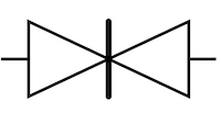
Figure 3: Gate valve symbol
Advantages
- A gate valve's straight, unobstructed path leads to minimal pressure loss through the valve.
- A gate valve takes up a small amount of space along the length of the piping.
- These valves work well with larger-diameter piping due to their simple construction. They are relatively easy to scale to larger sizes.
- A gate valve's simple design results in the valve being relatively durable.
- Gate valves operate slowly, reducing the possibility of water hammer in the system.
Comparing other valve types
Ball valves
Ball valves are excellent for on/off control, with low-pressure drop and quick operation. They can also regulate flow but are not as precise as other valve types, such as needle valves. Read more in our gate valve vs. ball valve article.
Globe valves
A globe valve is best for precise flow control and throttling but has a higher pressure drop. More about the differences between globe valves vs. gate valves can be found in our article.
Butterfly valves
Butterfly valves are versatile for on/off and throttling applications, with a compact design and low-pressure drop. For more information, read our article on gate valve vs. butterfly valve. Each type of valve has its own advantages and is suited for different applications based on the system's specific requirements.
Brass gate valves
Brass is the most popular housing material for gate valves due to several beneficial properties:
- Corrosion resistance: Brass is highly resistant to water corrosion, making it ideal for plumbing applications. This resistance ensures a longer lifespan for the valve, reducing maintenance and replacement costs.
- Thermal conductivity: Brass has good thermal conductivity, which helps in applications where temperature changes are frequent. It can quickly adapt to temperature variations without significant expansion or contraction, maintaining a tight seal.
- Cost-effectiveness: While not the cheapest, it is more affordable than other corrosion-resistant materials like stainless steel, making it a cost-effective choice for many applications.
- Aesthetic appeal: Brass is attractive and can be considered in applications where the valve is visible, such as in decorative plumbing fixtures.
- Non-sparking: Brass is a non-ferrous metal that does not produce sparks when struck. This property is important in applications where flammable gasses or liquids are present, as it reduces the risk of ignition.
- Biostatic properties: Brass has natural antimicrobial properties, which can be beneficial in applications involving potable water, as it helps reduce the growth of bacteria and other microorganisms.
Applications
Gate valves have numerous industrial and residential applications.
- Slurries: This valve has an unobstructed passageway for the fluid, so the slurry can easily pass through the valve.
- Viscous media: The unobstructed passageway allows viscous media like light grease and oil to flow easily. The valve can be pigged, a common cleaning method for these applications. In addition, valves for these applications are typically on or off for long periods.
- Water gate valves: Water gate valves are commonly used for water applications since flow control is typically not done. The valve can be fully open or fully closed, allowing for proper water control.
Selection criteria
Consider the following criteria when selecting a gate valve:
- Connection size: The connection size needs to match the size of the piping it connects to.
- Max pressure at 20 °C/68 °F: Exceeding the valve's max operating pressure can damage it and reduce its lifetime.
- Compression class: Compression class (e.g., PN10 or PN20) indicates the max pressure (bar) the valve can handle under normal operation.
- Hand wheel height (mm): The hand wheel sticks out above the body of the gate valve. Know how this affects the valve's total height when in the closed and open positions.
- Valve bore (mm): The internal diameter of the valve.
Installing a threaded gate valve
Installing a threaded gate valve is a straightforward process, but it requires careful attention to detail to ensure a secure and leak-free connection. Here’s a step-by-step guide to help through the installation:
- Gather necessary tools and materials: Before starting, gather all the necessary tools and materials, including the threaded gate valve, pipe wrenches, pipe sealant or Teflon tape, and any additional fittings required for the specific setup.
- Prepare the pipes: Ensure that the pipes connecting to the valve are clean and free from debris. Inspect the threads for any damage that could affect the seal.
- Apply sealant: Apply a suitable pipe sealant or Teflon tape to the male threads of the pipe. Wrap the tape in the direction of the threads to ensure it doesn’t unravel when screwing on the valve.
- Attach the valve: Carefully screw the threaded gate valve onto the pipe by hand to avoid cross-threading. Once it is hand-tight, use a pipe wrench to tighten it further. Be cautious not to overtighten, as this can damage the threads or the valve body.
- Align the valve: Ensure the valve is aligned properly with the flow direction indicated on the valve body. This is crucial for the valve to function correctly.
- Test for leaks: Once installed, test the connection for leaks by slowly turning on the system and checking for any signs of water or air escaping. If leaks are detected, tighten the connections slightly or reapply sealant as needed.
Maintaining a gate valve
Maintaining a gate valve is essential to ensure its longevity and reliable performance. Regular maintenance can prevent leaks, ensure smooth operation, and avoid costly repairs or replacements. Here are some key maintenance practices:
- Regular inspection: Periodically inspect the valve for signs of wear, corrosion, or damage. Check for leaks around the threads and the valve body.
- Operate the valve: Occasionally operate the valve to ensure it opens and closes smoothly. This prevents the valve from seizing due to infrequent use.
- Lubrication: If applicable, lubricate the valve stem and other moving parts to ensure smooth operation. Use a lubricant that is compatible with the valve materials and the fluid being controlled.
- Clean the valve: Keep the valve and surrounding area clean to prevent debris from interfering with its operation. If the valve is exposed to harsh environments, consider protective measures to shield it from damage.
- Check for corrosion: If the valve is used in a corrosive environment, regularly check for signs of corrosion and take appropriate action, such as applying a protective coating or replacing the valve if necessary.
FAQs
What is a gate valve?
A gate valve is a control valve that either allows media to flow through unobstructed or stops the fluid flow.
How does a gate valve work?
A gate valve works by rotating the stem (manually or with an actuator) to raise or lower a gate. The gate either allows unobstructed fluid flow or stops it.
What are gate valves used for?
Gate valves are used to allow for unobstructed fluid flow or to stop the fluid flow.
