


Ball Valve Symbols
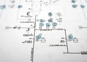
Figure 1: Piping and instrumentation diagram (P&ID)
A piping and instrumentation diagram (P&ID) gives a schematic representation of the piping and connected components like valves, vessels, and instrumentation of a physical process flow. Instead of detailed product images, unique symbols are used to represent various elements in the process to highlight connections and functional aspects. The P&ID is the fundamental schematic drawing used for laying out the installation of a process control system. This article discusses the main symbols of ball valves used in a P&ID with a typical example. Read our ball valve overview article for more information on the design and working of ball valves.
Table of contents
- What is a process and integration diagram (P&ID)
- 2-way ball valves
- 3-way and 4-way ball valves
- Actuated ball valve
- End connections
- Standardization of symbols
- Ball valve application in P&ID
View our online selection of ball valves!
What is a process and integration diagram (P&ID)
A process and integration diagram (P&ID) is a comprehensive visual representation of a process system. These diagrams include standard symbols that explain:
- Identification of components
- How instruments and components are connected
- Where instruments are located within a process system
- Individual instrument’s function within a process
The symbols drawn in a P&ID are not intended to be dimensionally accurate. The individual symbols can also be marked with letters, words, and numbers for more details.
A P&ID illustrates a system’s process, and it is used for the design and maintenance of the manufacturing process they represent. These diagrams are vital for troubleshooting and process monitoring within an industry. P&IDs use basic symbols to define the function of each component within a process. The symbols used to represent ball valves are discussed in the next section.
2-way ball valve symbol
A 2-way on/off valve is symbolized by two equilateral triangles pointing towards each other. The flow direction of the fluid is designated by an arrowhead at the end of the line (See Figure 2 Left). A 2-way ball valve is represented by two equilateral triangles pointing toward each other with a ball at the center, as seen in Figure 2 Right.
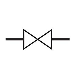
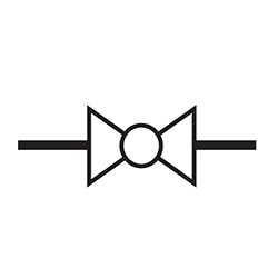
Figure 2: A general 2-way valve (left) and ball valve icon (right)
3-way and 4-way ball valve symbols
Additional triangles are added to the valve symbol of multiport valves like 3-way and 4-way valves. T-port and L-port valves are symbolized by lines within the ball symbol. The flow path is shown by small arrows beside the symbol. Figure 3 shows the various symbols used in multiport valves.
- A: A general 3-way valve
- B: A general 4-way valve
- C: A 3-way ball valve with L-port. Note the ‘L’ symbol within the ball
- D: A 3-way ball valve with T-port. Note the ‘T’ symbol within the ball
- E: A 3-way ball valve showing the fluid flow direction using an arrow
- F: A 3-way ball valve showing the fluid flow direction using an arrow
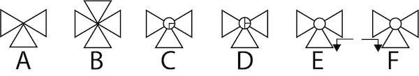
Figure 3: Multi-port ball valve symbols: general 3-way valve (A), general 4-way valve (B), 3-way ball valve with L-port (C), 3-way ball valve with T-port (D), and a 3-way ball valve showing the fluid flow direction using an arrow (E & F).
Actuated ball valve symbol
For actuated ball valves, the actuation type is shown with lines protruding from the center of the valve. A small symbol at the top of the line helps in further identification. Hydraulic and electric actuators are denoted with letters. Figure 4 shows the various symbols used for actuated ball valves. Note the lines drawn from the ball indicating the actuation mechanism used.
- A: Manually operated ball valve symbol
- B: Pneumatically actuated ball valve (Diaphragm type) symbol
- C: Pneumatically actuated ball valve (Rotary piston type) symbol
- D: Electrically actuated ball valve symbol
- E: Hydraulic actuator ball valve symbol
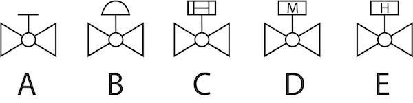
Figure 4: Actuated ball valve symbols; manually operated ball valve (A), pneumatically actuated ball valve (diaphragm type) symbol (B), pneumatically actuated ball valve (rotary piston type) symbol (C), electrically actuated ball valve symbol, and a hydraulic actuator ball valve symbol (D).
Failsafe positions
Actuators with fails-afe options are shown by an arrow and line either pointing away from the ball (fail-safe open) or towards the ball (fail-safe closed). These can also be symbolized with the letters ‘FC’ (failsafe closed) or ‘FO' (failsafe open).
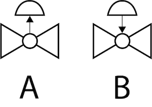
Figure 5: Failsafe closed (A) and failsafe open (B) ball valve actuators
End connections
The valve connected type (threaded, flanged, welded, or socket weld) is symbolized using circles, perpendicular lines, and squares, as seen in Figure 6. Read our article on ball valve connection types for more details on the various types used in ball valves.
- A: Flanged connection are shown with a perpendicular line indicating that the valve can be removed without affecting the pipe.
- B: A temporary threaded connection are shown by unfilled circles.
- C: Permanent welded connections are shown by filled-in squares.
- D: Socket-welded connecteions are shown by using unfilled squares.
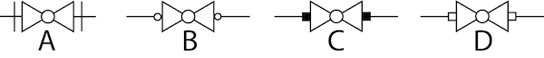
Figure 6: Symbols showing end connections of a ball valve; flanged connection symbol (A), threaded connection symbol (B), permanent welded connection symbol (C), and socket-welded connection symbol (D)
Standardization of symbols
The International Society Of Automation (ISA) has stipulated a strict set of standards for P&ID symbols, but still, there are different ways of representing valves. There are transparent discrepancies between valve types across various companies and libraries within a simulation tool. But this is not a protruding issue because all components are also described by text, a unique model called the part number, a tag number which is a specific component in the system, and are described in detail in a legend that goes along with the drawing. Be consistent with the symbols throughout the drawing so that the P&ID diagram can be easily comprehended by everyone who works with it.
P&ID symbol example
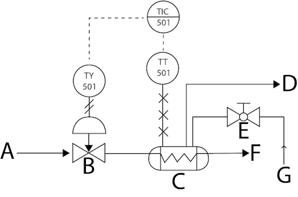
Figure 7: A P&ID for a heat exchange process: input steam (A), control valve (B), heat exchanger (C), heated product output (D), manually operated ball valve (E), steam output (F), and input product (G).
Figure 7 shows an example of P&ID for a heat exchange process.
- Ball valve (Figure 7 labeled E): A manually operated ball valve directs the incoming product (Figure 7 labeled G) through a pipe (plain straight lines indicate pipes) into a heat exchanger (Figure 7 labeled C).
- TT 501: TT 501 is a temperature transmitter that transmits the heat exchanger’s temperature recorded by a temperature sensor over an electrical line. The number following TT is the loop number. Hence, TT 501 is the temperature transmitted in loop 501 that gives an idea about the location and function of the instrument.
- TIC 501: The temperature transmitter sends the temperature value over an electric line (shown by dotted lines) to a temperature indicator and controller, TIC 501, located in a control room.
- TY 501: Based on the set point in TIC, it sends an electrical control signal to the temperature relay, TY 501, located in a field or plant. TY 501 is a current to pneumatic signal converter. The pneumatic signal acts on the control valve. The double slanted lines at the output of TY 501 indicate a pneumatic transmission line.
- Control valve (Figure 7 labeled B): The control valve has steam at its input ports (Figure 7 labeled A). The pneumatic control valve then opens, closes, increases, or decreases steam flow into the heat exchanger.
- The heated product is carried out for further applications (Figure 7, labeled F).


