Ball Valve Circuit Functions
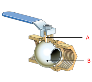
Figure 1: A cross-section of a manual ball valve where A is the stem and B is the ball.
The circuit function of a ball valve refers to the flow direction within the ball valve. Common ball valve circuit functions are 2-way or 3-way. There are additional circuit functions, like the 4-way or 5-way, but these are not covered in this article. This article explores the design, operation, and application of 2-way and 3-way ball valves.
2-way ball valve
For a 2-way ball valve, the flow direction is from the input to the valves output. The flow can be closed by turning the valve handle perpendicular to the direction of flow. Therefore, turning the valve handle in line with the flow will open the valve. If the handle/ball is partially turned, you can throttle the flow (partial flow) as seen in Figure 2. 2-way ball valves are considered in line with the rest of the system. A non-inline ball valve works with the same principle, but handle orientation in regards to the flow direction for closed/open is slightly different. Keep in mind that the handle of an inline and a non-inline ball valve moves only 90°, therefore the position is important when installing.
2-way ball valves are available for a wide variety of media and are available as manual operation or with an ISO 5211 top, allowing you to mount an electrical or pneumatic actuator to the 2-way valve.
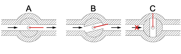
Figure 2: A manual operated 2-way in-line ball valve in a fully open position (A), a throttled position (B), and closed position (C). The red line indicates the handle or actuator position.
3-way ball valve
3-way ball valves have three ports and are available with either an L or T-port design. The L and T designation refers to the internal bore design, which will determine the medias flow direction. A 3-way ball valve with a T or L port allows for mixing, distribution, or diverting the flow direction for different applications.
3-way ball valve T-port
A 3-way T-port valve can be used for mixing media from two inlets into a single outlet or for distributing one inlet to two outlets. By changing the position of the handle, you can change the circuit function.
Figure 3 below shows the circuit functions for T-port ball valves which have handles that can turn 90°. View Tamesons selection of three-way T-port ball valves here.
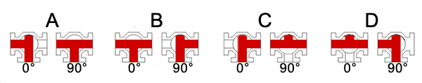
Figure 3: A: T-port ball valve with a handle that turns 90° with the possible circuit functions per flow plan (A, B, C, D), and handle position (0°, 90°)
The below image shows the circuit functions for T-port ball valves which have handles that can turn 180°
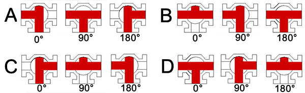
Figure 4: B: T-port with a handle which turns 180° with the possible circuit functions per flow plan (A, B, C, D), and handle position (0°, 90°, 180°)
3-way ball valve L-port
The 3-way L-port valve is designed for flow direction control. The L-port valve has a 90° bore inside of the ball, hence the name L-port. An example of an application is to have two inputs from separate tanks and one output and you want to only use one of the inputs but always the one output.
The below image shows the various circuit functions of an L-port ball valve with both 90° and 180° handles. Ones with 180° turn allow you to disconnect both inputs from the output, allowing for no flow. View Tamesons selection of L-port 3-way ball valves here.
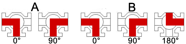
Figure 5: The circuit functions of a 90° (A) and 180°(B) 3-Way L-port ball valve, the various handle positions are indicated with 0°, 90°, and 180°
The use of 3-way valves is more cost-effective than the use of multiple 2-way valves. Like 2-way valves, 3-way ball valves are available as manually operated and are also available with an ISO 5211 top, allowing you to mount an electrical or pneumatic actuator to the 3-way valve.
Use-specific valves
There are other ball valves that are specifically used for one purpose. For example, hydraulic ball valves have been designed specifically for hydraulics. There are 3-way hydraulic ball valves for high-pressure applications. The valves provide flow direction control of hydraulic and heating oil up to a maximum pressure of 500 bar (7252 psi).
Another example is ball valves for vacuum applications. A suitable vacuum ball valve should possess several characteristics for operation in a vacuum environment. The most important characteristics are the ability to have very good sealing properties in the shut-off position, quick response time, and the ability to operate at pressure differences between the sides of the valve. Due to the specialized characteristics needed in vacuum applications, it is important to know the circuit functions and bore preferences of the valve you choose. For more information read our article on ball valves for vacuum applications, or our guide to ball valves.