


Pneumatic Cylinder Sensors - How They Work
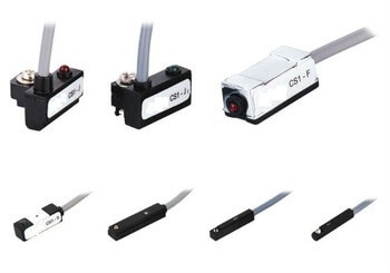
Figure 1: Different pneumatic cylinder proximity sensors
Sensors are essential for providing position feedback to control systems in automated machinery and equipment. In pneumatic cylinders, sensors are used to detect the linear position of the piston, which is critical for applications requiring precise position feedback. The most common sensors for pneumatic cylinders are magnetic proximity sensors, which sense the magnetic field of a magnet embedded in the cylinder piston. These sensors are mounted on the body of the pneumatic cylinder and indicate "ON" or "OFF" based on their proximity to the magnet. Depending on the specific application, various magnetic proximity sensor technologies can be employed to optimize performance, space, and reliability. Figure 1 illustrates examples of different pneumatic cylinder proximity sensors.
Reed sensors are the most common type of pneumatic cylinder sensor. They have been used for years and are proven technology. The two main cause of concerns for a reed sensor over other sensors discussed below are life-time and shock/vibration concern. Reed sensors typically have a life cycle of over 10 million and typically the reed sensor isn’t the first to fail when it is in a high shock or vibration applications. For these reasons, reed sensors have been and still are the most popular pneumatic cylinder sensor.
View our online selection of pneumatic cylinder sensors!
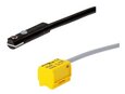
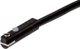
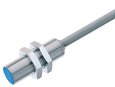
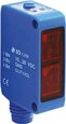
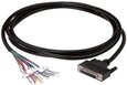
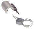
Table of Contents
- Why use a sensor for a pneumatic cylinder?
- Pneumatic cylinder sensor mounting
- Magnetic proximity sensor options
- How do you select between sensors?
- Pneumatic cylinder sensor comparisons
- Buy position sensors online
Why use a sensor for a pneumatic cylinder?
Pneumatic cylinder linear position sensors are used to detect the linear position of the piston during operation. Pneumatic cylinders are typically made with a magnet already attached internally to the piston, so that the use of magnetic proximity sensors can be used if desired. Depending on where the sensor is mounted, it can detect extension, retraction, or individual positions along the cylinder body. Multiple sensors can also be attached to one pneumatic cylinder for multiple position feedback locations. Pneumatic cylinders with position sensors allow for added security and feedback to ensure the piston location for crucial applications.
Pneumatic cylinder sensor mounting
The two most common types of pneumatic cylinder body types are profile, like ISO 15552, or round, like ISO 6432. Depending on the body type, there are different mounting methods. Mounting methods can also change with different sensor types, so it is important to understand the type of cylinder body you have with the sensor type.
Profile cylinders
Profile cylinders are rectangular in shape and have two easy methods to mount sensors to the cylinder’s body. For pneumatic cylinders that adhere to ISO 15552, there are grooves along the body to inset a sensor as seen in Figure 2. The sensor (1) is then fastened into place with a set screw (2) by a screw driver (3). Other profile cylinders have tie rods, which run the length of the cylinders body on all four corners. Sensors can be mounted onto the tie rod and slid to the appropriate position along the cylinder’s length.
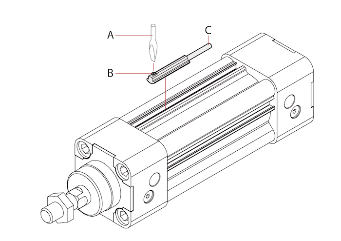
Figure 2: ISO 15552 pneumatic cylinder with a sensor (C) mounted via set screw (B) with a screw driver (A)
Round cylinders
Round cylinders are generally smaller, like ISO 6432, but sensors can still be mounted to them by using a circular band to go around the cylinder’s housing. The band needs to be specified in accordance with the cylinder’s diameter. Once mounted, the sensor and band can slide along the length of the cylinder and then fastened into place. An ISO 6432 pneumatic cylinder with a sensor mounted on it can be seen in Figure 3.
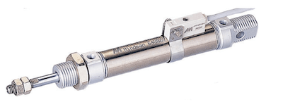
Figure 3: ISO 6432 pneumatic cylinder with a sensor mounted
Magnetic proximity sensor options
All sensors that are used for pneumatic cylinders for feedback on linear position of the piston utilize a magnetic field. Therefore, typically all pneumatic cylinders already have a magnet located internally on the piston. However, it is still important to verify this design specification for your pneumatic cylinder if linear position feedback is required.
Reed switch
A reed switch sensor is a magnetic proximity sensor that is switched “ON” when an axially aligned magnetic field is applied to it. The magnetic poles of an axially aligned magnet are next to each other in the axial plane. As the axially aligned magnet approaches the reed sensor a magnetic field parallel to the reed switch is generated. A reed switch is composed of a pair of ferromagnetic metal reeds, which are enclosed in a sealed glass tube. Without the presence of a magnetic field (top image Figure 4) the metal reeds will be separated, and the sensor will be switched “OFF". When the cylinder piston passes the switch and applies a magnetic field strong enough to attract the reeds together (middle image Figure 4), the sensor will become switched “ON” (bottom image Figure 4).
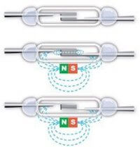
Figure 4: Reed switch operation
Compared to other sensor options, reed switches are cost effective and can be operated with AC or DC voltages. Additionally, reed switch sensors have a low power consumption which makes them suitable for applications with power consumption requirements. Due to the mechanical nature of switching reed contacts, reed switch sensors do have limitations. First, the switching contacts have a finite number of switching cycles and will require maintenance over the lifespan of the machine. Next, reed switch sensors are not suitable for applications which are exposed to high vibration or shock. High shock and vibration could cause the reed contacts to chatter causing inaccurate signaling. The switching characteristics of a reed switch can also cause unintended double switching. Double switching is when the sensor output switches “ON” and “OFF” twice while the cylinder magnet passes the reed switch once. The false double switch of the sensor output is due to the non-uniform strength of a magnets force field. The strength of a magnet field is strongest at each pole of the magnet and weakest at the center between each pole. If the piston magnet is not strong enough, it may cause the switch output to double switch as it passes across the sensor. Finally, in compared to solid-state sensors, reed switches are relatively slow to activate which makes them unsuitable for applications which need fast response times. However, reed switch sensors for pneumatic cylinders are widely used due to them being relatively inexpensive compared to other sensors, require no standby power, can function with either DC or AC loads, and are a proven known solution.
Hall effect sensor
A hall effect sensor is a magnetic proximity sensor that is switched “ON” when a radially aligned magnetic field is applied to it. A radially aligned magnet will produce a magnetic field perpendicular to the magnetic field of the hall effect sensor as seen in Figure 5. Unlike reed switches, hall effect sensors are solid-state devices and designed with different components. Reed switches depend on moving mechanical contacts to provide sensor output. Solid-state devices provide sensor output by using electrical circuits without moving components. A hall effect sensor consists of a semiconductor with a continuous current flow through it, which can be seen in the top image in Figure 5. When a magnetic field is applied radially (2) to the current flow (1) as seen in the bottom image in Figure 5, the charged electrons separate to opposite sides of the semiconductor based on polarity. The separation of charged electrons induces a voltage across the hall effect circuit (4). Once the output voltage across the circuit is greater than the switching threshold the sensor output is switched “ON”, which can be seen in Figure 5.
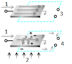
Figure 5: Hall effect sensor operation: current flow (1), magnetic field (2), voltage = 0 (3 & 4)
Unlike reed switch sensors, hall effect sensors do not include moving components and will have a smaller mounting footprint. The solid-state design increases the lifespan of the sensor due to its wear free operation and also makes them resilient to shock and vibration. Without the need to overcome the inertia of mechanical components, hall effect sensors are also suitable for time-critical application which require fast switching. Similar to reed switch sensors, magnet orientation is important for proper operation. Additionally, hall effect sensors have low sensitivity. Depending on the diameter and thickness of the cylinder body the switching output may not activate properly. Similar to reed switches the double switch points are also possible due to the sensors low sensitivity.
Anisotropic magnetoresistive sensor
An anisotropic magnetoresistive sensor (AMR) is a solid-state magnetic proximity sensor that is switched “ON” when a radial or axial magnetic field is applied to it. An AMR circuit consists of a Wheatstone bridge circuit (Figure 6) to measure resistance. The resistance of an AMR sensor will decrease with the strength of the magnetic field, which results in a greater voltage gradient across the AMR circuit. Once the voltage across the circuit is greater than the switching threshold (Figure 6 number 3), the sensor output is switched “ON” as seen in Figure 6 number 4.
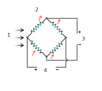
Figure 6: AMR sensor operation: magnetic field (1), applied magnetic field (2), bias voltage (3), and voltage = 0 (4)
Similar to hall effect sensors, AMR sensors are fast acting, wear free, and are resilient to shock and vibration. The benefit of AMR sensors is they are less sensitive than hall sensors and respond well to changes in magnetic field strength. This results in improved piston detection over greater distances due to its ability to detect weaker magnet fields. The possibility of double switch points is eliminated due to the higher sensitivity. Additionally, sensors will detect axially and radially magnetized magnets. AMR sensors are more compact than reed switch sensors and are cost competitive. A disadvantage of AMR sensors is that they typically continuously draw current. For applications with low-power requirements a reed switch sensor may be a more suitable sensor choice.
Giant magnetoresistive sensor
A giant magnetoresistive sensor (GMR) is a solid-state magnetic proximity sensor that is switched “ON” when a radial or axial magnet field is applied to it. A GMR sensor is composed of varying layers of alternating magnetic and non-magnetic conductive layers as seen in Figure 7 numbers 2 and 3. Similar to an AMR sensor, when a magnetic field is applied to the sensor the resistance properties of the circuit change creating a higher voltage gradient across the circuit as the magnetic field increases. For example, in the presence of a magnetic field (Figure 7 number 1) the resistance of the circuit decreases allowing current to flow (Figure 7 number 4) and the voltage across the circuit increases. Once the voltage across the circuit is greater than the switching threshold the sensor output is switched “ON”.
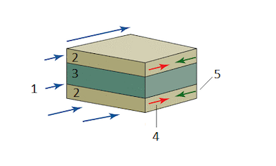
Figure 7: GMR sensor operation: applied external magnetic field (1), ferromagnetic layer (2), conductive non-magnetic layer (3), low resistance with magnetic field applied (4), and high resistance with no external magnetic field (5)
GMR sensors offer similar benefits to AMR sensors, however, they are even more sensitive to the presence of a magnetic field. High sensitivity also allows for a highly compact sensor, which is suitable for smaller and shorter cylinders. Although high sensitivity is a benefit for applications which need immediate sensor feedback, it may cause unintended output signaling if disturbed by surrounding magnetic fields. For example, environments with nearby high power (AC motors or AC incoming power) may disturb the sensor signal and cause unintended error.
How do you select between sensors?
For the majority of applications, a reed sensor is typically chosen. They are proven technology and have a long enough life cycle and vibration resistance to handle common applications. However, other criteria to consider for special applications are:
- Environment: Will the cylinder be exposed to large amounts of vibration or shock? If so, a solid-state sensor will reliably operate without output chatter. Common solid-state sensors are hall effect, AMR and GMR sensors. In addition, will the sensor be in an enclosed clean environment or does it require a high protection housing, like IP67. Temperature considerations should also be taken into account.
- Switching Speed: How critical is output switching speed to your application? Solid-state sensors offer a faster switching time. Common solid-state sensors are hall effect, AMR and GMR sensors.
-
Output Type: What output signal type is required of the control system? PNP and NPN output signals are available for solid-state devices.
- PNP: A PNP output provides a path to supply positive power to the output. This is also commonly known as “sourcing sensors”. PNP is considered more common in North America and Europe.
- NPN: A NPN output provides a path to supply to ground. This is also commonly known as a “sinking sensor”. NPN is considered to be more popular in Asia.
- Switching Signal Characteristics: What is the switching power and current requirements of the control system? The selected sensor should be compatible for proper operation.
- Mounting: What mounting options are available for each cylinder type? Depending on if you have a profile cylinder with grooves or tie rods or if you have a round cylinder, the mounting types change.
- Magnet Orientation: Reed switch and hall effect sensors require correct orientation of the applied magnetic field for proper operation. Therefore, the sensor must be mounted in the proper orientation to the piston.
- Circuit Protection: If needed, sensors can incorporate circuit protections, like short-circuits, reverse polarity, and surge protection.
- Wiring: Wiring of the power supply to the sensor will differ depending on if the sensor is a solid-state sensor (ie. AMR, GMR, hall effect) or a reed sensor. An LED to indicate correct wiring is often available for each sensor. For example, if the polarity of the power supply to a reed switch is reversed the LED at the sensor will not illuminate. Reed switch sensors generally have a 2-wire configuration whereas solid-state sensors have 3-wires. In addition to a positive and negative wire, a third wire will be used for connection to the load. Correct wiring of the load wire should always be verified before applying power as miswiring can permanently damage the sensor.
Pneumatic cylinder sensor comparisons
| Reed Switch | Hall Effect | AMR | GMR | |
| Size | Large | Small | Medium | Small |
| Construction | Mechanical | Solid State | Solid State | Solid State |
| Magnet Strength Required | Medium | High | Low | Low |
| Sensitivity | Medium | Low | High | High |
| Temperature Stability | Medium | Low | Medium | High |
| Power Consumption | Zero | Low | High | Low |
| Noise Immunity | High | Low | High | High |
| Switching Speed | Low | High | High | High |
| Mechanical Robustness | Low | Medium | High | High |
| Electrical Robustness | Low | Low | High | High |
| Double Switch Points | Yes | Possible | No | No |
Read our pneumatic cylinders article for more information on the working and types of pneumatic cylinders.


