


Well Pump Check Valve
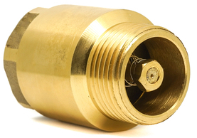
Figure 1: Brass check valve for well pump
Check valves prevent water from flowing back into the well when the pump turns off. They prevent issues such as backspin, water hammer, and upthrust, which can damage the pump or motor and reduce their lifespan. This article discusses the features of well pump (jet and submersible) check valves, guidelines for their installation, and standard troubleshooting techniques.
Table of contents
- How to select a well check valve
- Installing a check valve for a jet pump
- Submersible pump check valves
- Signs of a faulty well pump check valve
- Troubleshooting low pressure and constant cycling
- Troubleshooting a pressure tank not filling up
View our online selection of check valves!


How to select a well check valve
Material
The check valve material must resist corrosion from minerals, salts, and chemicals in well water. This is critical for both submerged and surface applications. The material should also withstand the specific pressure and temperature conditions of the well system.
Table 1: Materials for water well check valve
| Material | Use | Advantages | Considerations |
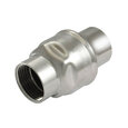
| Stainless Steel (304/316) | Suitable for both submerged and surface applications | Excellent corrosion resistance, especially in aggressive or saline environments. High strength and durability | Higher cost compared to other materials |
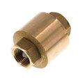
| Brass | Common in surface applications and potable water systems | Good corrosion resistance in freshwater. Cost-effective | Not ideal for highly acidic or saline conditions |
| PVC (Polyvinyl Chloride) | Suitable for low-pressure applications and standard residential well systems | Lightweight, corrosion-resistant, and cost-effective | Adequate for typical well pump systems but less durable than metals |
Check valve type
Well pumps use spring-loaded check valves because they are designed to operate quickly. They close rapidly with the pump shutoff. Swing-type check valves can cause water hammer on well pump systems. A spring check valve can be installed horizontally or vertically. However, ensure that the flow direction is correctly aligned with the system's water flow.
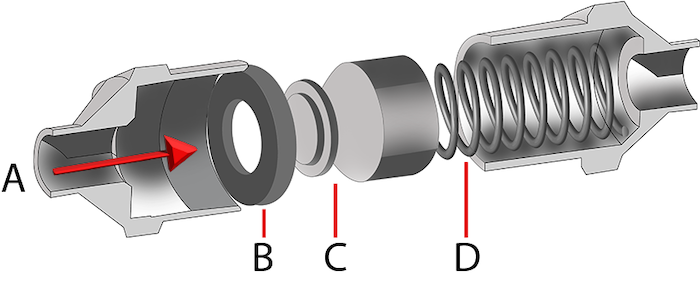
Figure 2: Spring-assisted check valve: flow direction (A), o-ring (B), poppet (C), and spring (D).
Pressure rating
For most residential systems, well pumps operate within a 2 to 4.13 bar (30 to 60 PSI) pressure range. The check valve's pressure rating should exceed the pump's maximum output pressure.
Size and connection type
The most common check valve sizes for well pump systems range from 12.7 mm to 102 mm (1/2 inch to 4 inches) in diameter and should match the well pump piping. Threaded check valves are easy to install on well piping and are therefore commonly used.
Installing a check valve for a jet pump
Jet pumps are typically installed above ground and use a combination of suction and pressure to lift water. They are particularly suited for shallow wells (around 15 meters or 49 feet) and use a single check valve or foot valve.
Foot valve
A foot valve is installed at the bottom of the well, below the static water level, ensuring it is submerged. A foot valve has a strainer attached to its inlet port. The strainer prevents dirt and debris from entering the valve and the pump, reducing the risk of clogging and damage to the pump.
With the foot valve at the bottom, the water column above the foot valve remains intact. Hence, the pump can be easily primed using the priming plug on the pump itself. This allows the pump to draw water efficiently without introducing air.
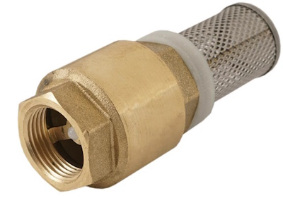
Figure 3: Brass foot valve
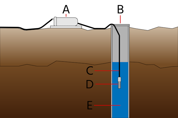
Figure 4: Installation of a foot valve in a shallow well: Water pump (A), well (B), water pipe (C), foot valve (D), and water (E).
Check valve above the ground
To simplify maintenance, check valves are often installed above ground, close to the pump. This approach can be more accessible than using a foot valve in a narrow pipe. However, when the check valve is above ground, additional fittings are needed to prime the pump, as the water column is not maintained like a submerged foot valve.
Submersible pump check valves
Submersible pump systems are typically used for deeper wells. These systems use multiple check valves for two reasons:
- Prevent excessive pressure on a single valve to reduce the risk of failure.
- In a 183-meter (600-foot) deep well, staging check valves at 61-meter (200-foot) intervals ensures each valve handles only a portion of the total pressure. This significantly reduces the risk of failure and ensures smooth operation.
- Staging helps prevent water hammer, which can occur if a lower valve fails. Multiple check valves minimize the impact of such failures, protecting the system from sudden pressure surges.
How to position check valves in a deep well
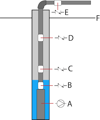
Figure 5: A submersible well pump system: pump (A), check valve (B) is installed at the pump’s discharge head. Check valves (C and D) are separated by at most 61 meters (200 feet). Check valve (E) is installed above ground level (F).
Here are key guidelines for positioning check valves in a deep well:
-
First check valve (Close to pump)
- Install it within 7 meters (25 feet) of the pump.
- Make sure it’s below the water’s drawdown level (the level water drops to when pumping).
- This is especially important if your pump doesn’t have a built-in check valve.
-
Additional check valves (For deeper wells)
- If your well is deep, add a check valve every 61 meters (200 feet).
- This helps manage pressure and prevents water from flowing backward through long pipe runs.
-
For slow-producing wells
- Place the first check valve about 1.5 meters (5 feet) above the pump.
- This gives the pump space to push out air, helping to avoid airlocks.
- But don’t place any check valve more than 7 meters (23 feet) above the lowest water level, as it needs to stay underwater to work correctly.
-
Surface or horizontal piping
- Add a check valve at the surface or just below the well seal, especially for horizontal runs.
- If the lower valve fails, the upper one could be hit by water hammer.
Signs of a faulty well pump check valve
Well pump check valves can fail due to wear and tear, corrosion, debris buildup, or improper installation. Here are some common signs that may indicate a faulty check valve in your well pump system:
- Frequent pump cycling
- Low water pressure at faucets and fixtures
- Unexpected rise in electricity bills
- Unexplained wet areas or water pooling around the well, pipes, or yard
- Unusual sounds near the well or pipes, such as hissing or spraying
- Changes in water quality, like taste, color, or odor
- The pressure tank not filling up
Troubleshooting low pressure and constant cycling
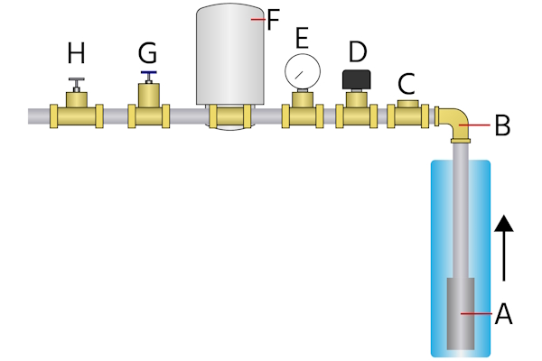
Figure 6: Typical well plumbing system for submersible pump: submersible well pump (A), well head (B), check valve (C), pressure switch (D), pressure gauge (E), pressure tank (F), hose bib (G), and gate valve or ball valve (H).
A faulty check valve allows water to flow back into the well, causing the tank's (Figure 7 labeled F) pressure to drop. The pressure switch (Figure 7, labeled D) repeatedly turns the pump (Figure 7, labeled A) on to restore pressure, resulting in constant cycling.
A slight decrease in pressure indicates that the check valve (Figure 7 labeled C) has malfunctioned but not failed. A total failure would result in the pressure dropping to zero, and the pump would continuously cycle on and off.
How to determine a potential leak in a well pump system
If you notice a drop in water pressure at home, it could be due to a faulty check valve or a leak in the system. Perform the following steps to check for leaks in a system:
- Turn off all water outlets in the building. If the pressure continues to drop, it suggests a possible leak.
- Listen for sounds caused by the leak:
- In the well: If the leak is in the well, you might hear hissing or spraying sounds at the top, indicating water is escaping.
- In the pipe: If the leak is in the underground pipe between the house and the well, look for wet spots along the pipe's path.
Note: it may not always be possible to hear the sounds, especially if the leak is underground or if ambient noise is high.
Diagnosing the leak
- Close the isolation valve: The isolation valve is located just before your home's plumbing. Closing it isolates the plumbing from the well system, allowing you to focus on the well system itself.
- Turn off the pump: With the isolation valve closed, turn off the pump. This will help you see if the system can maintain pressure without the pump running.
-
Monitor pressure over time:
- If the pressure drops immediately after turning off the pump, it suggests that water is flowing back into the well, likely due to a faulty check valve.
- If the pressure drops gradually over time, it may indicate a leak somewhere in the system, such as in the pipes or the pressure tank.
By following these steps, you can determine whether the pressure drop is caused by a leak or backflow from a faulty check valve. Also, ensure the pressure tank is not waterlogged, as this can affect pressure stability.
Examining multiple check valves in submersible pumps
Start by inspecting any check valve near the pressure tank or at the wellhead. These are the easiest to access and check for debris or damage. If the surface check valve is functioning correctly, the issue might be with the check valve at the submersible pump or along the riser pipe.
It may be necessary to pull the pump to diagnose deeper check valves. This often requires professional assistance. Once the pump is out, inspect the check valves for wear or damage and replace them if necessary.
Troubleshooting a pressure tank not filling up
Water is pumped from the well into the pressure tank, from where it is distributed throughout the building. Sometimes the pressure tank fails to fill up even though water is pumped out of the well.
In this case, see if the check valve is installed backward. Typically, an arrow on the valve's housing indicates the direction of flow. If there isn't an arrow, examine the valve to ensure it is installed in the intended flow direction.
Also, verify that the pump is functioning correctly and check the pressure tank's settings. Ensure the tank's air pressure is set to 0.14 bar (2 PSI) below the cut-in pressure of the pressure switch (e.g., 2.6 bar (38 PSI) for a switch with 2.8 bar (40 PSI) cut-in pressure) when the tank is empty.


