


Relay Types and Working Principle
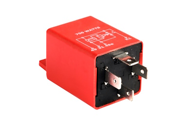
Figure 1: Electromechanical relay for automobiles
A relay is an electrically operated switch used to isolate circuits, switch between circuits, and control a high-power circuit with a low-power signal. Relays are categorized by their design and functionality, such as electromechanical, solid-state, and reed relays. This article explores the various types of relays, their working principles and discusses their diverse industrial applications.
Table of contents
- General terminology
- Based on poles and throw
- Based on operation principles
- Based on application
- Based on forms
- Applications
- FAQs
View our online selection of relays!
General terminology
There are four types of terminals in a relay:
- Control input (coil terminals): Two input terminals that control its switching mechanism.
- Common (COM): This terminal serves as the output for the relay and is where one side of the load circuit is attached. Internally, this terminal is linked to one of the other two terminals, which varies according to the relay's status.
- Normally Open: The normally open (NO) terminal is another load terminal on a relay that remains disconnected when the relay is inactive. The NO terminal connects with the Common (COM) terminal when the relay is activated.
- Normally Closed: The normally closed (NC) terminal is an additional load terminal on a relay. Under normal circumstances, without any control input, this terminal maintains a connection with the Common (COM) terminal. However, when the relay is activated, the NC terminal breaks its connection with the COM terminal and remains open until the relay is deactivated.
Read our relay applications article for more information on the working and wiring of industrial relays.
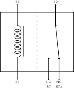
Figure 2: Relay terminals
Poles and throw
- Pole: The term 'poles' refers to the number of separate circuits the relay can switch or control. Each pole represents an individual switch within the relay; for example, a single-pole relay has one switch and can control one circuit, whereas a double-pole relay has two switches and can control two circuits independently.
- Throw: The term 'throw' indicates the number of positions each pole can connect to. This describes the number of outputs each switch can be connected to. For instance, a single-throw relay has one position per pole, meaning each switch can connect to only one output. In contrast, a double-throw relay has two positions per pole, allowing each switch to connect to one of two outputs.
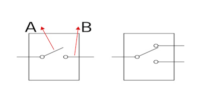
Figure 2: Single throw (left), double throw (right): pole (A) and throw (B)
Based on poles and throw
Table 1: Relay classification based on the number of poles and throw inside a relay.
| Relay type | Description | Diagram |
| SPST (Single pole single throw) | An SPST relay controls only one circuit (single pole). It has two positions: on and off (single throw). It connects or disconnects the circuit when flipped. |  |
| SPDT (Single pole double throw) | An SPDT relay controls only one circuit (single pole). It has two states; in each state, one of its circuits remains closed while the other stays open, and this condition is reversed in the alternate state. | 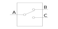 |
| DPST (Double pole single throw) | The term 'double pole' indicates that it has the capability to manage two entirely separate circuits independently. 'Single throw' signifies that each pole has a single conducting position. | 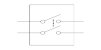 |
| DPDT (Double pole double throw) | The term 'double pole' signifies that it can control two distinct circuits, and 'double throw' implies that each pole can conduct in two different positions. | 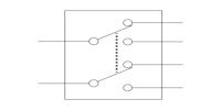 |
Based on operation principles
Relays are classified based on their operating principles into several categories.
Electromechanical relay
An electromechanical relay has a coil and a mechanically operated contact. Upon energizing the coil, a magnetic field is generated. This field pulls the armature (the moving contact) towards it. Conversely, when the coil is de-energized, it loses its magnetic field, and a spring pulls the armature back to its original position. Read our circuit breaker article for more details on the construction and operation of electromechanical relays.
The electromagnetic relay (EMR) can be used with an AC or DC power source, depending on the application. The construction of EMR relays for AC and DC varies slightly, particularly in the design of their coils.
The primary drawback of an electromagnetic relay (EMR) is that its contacts tend to create an electrical arc when they separate, which can cause an increase in contact resistance over time. This progressive increase in resistance consequently leads to a reduction in the relay's overall lifespan.
Solid state relay
A solid-state or electronic relay (SSR) consists of semiconductor components rather than mechanical elements. When a control signal is applied to a solid-state relay (SSR), an internal light-emitting diode (LED) illuminates, emitting infrared light. This light is detected by a photosensitive semiconductor component, which then transforms the light signal into an electrical signal, activating the circuit switch.
Solid-state relays operate at a relatively high speed and consume much less power than electromagnetic relays (EMRs). They also have a longer lifespan, owing to the absence of physical contacts that could wear out. However, a notable disadvantage of SSRs is the inherent voltage drop across the semiconductor, which results in power loss through heat dissipation. There are also hybrid relays made up of SSR and EMR relay types.
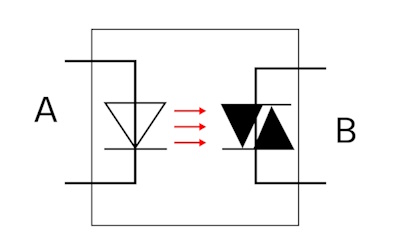
Figure 3: Solid state relay: control input (A) and load circuit (B)
Reed relay
A reed relay consists of a reed switch and an electromagnetic coil, often accompanied by a diode to protect against back electromotive force (back EMF). The reed switch comprises two slender metal reeds made from a ferromagnetic material, sealed within a glass tube (Figure 4 labeled C). This glass tube also supports the metal reeds and is filled with an inert gas to prevent oxidation and contamination. Upon energizing the coil (Figure 4 labeled B), the ferromagnetic metal blades within the reed switch are magnetically attracted to each other, creating a closed circuit. Since there is no moving armature involved, the issue of contact wear is virtually nonexistent. Additionally, the presence of inert gas within the sealed glass tube further extends the lifespan of the switch by preventing corrosion and other forms of degradation.
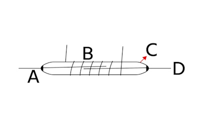
Figure 4: contact terminals (A, D), coil input (B), and glass tube (C)
Thermal relay
An electrothermal relay comprises a bimetallic (made up of two metals having different thermal expansion coefficients) strip. When the current flows through the conductor, it produces heat, causing the temperature of the bimetallic strip to rise and expand. The metal with a high thermal expansion coefficient expands more than the other. Due to this, the strip bends and closes the contacts to activate the trip circuitry. Thermal relays are usually used for electric motor protection.
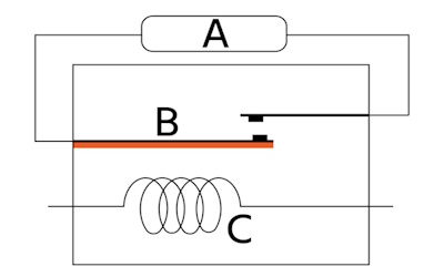
Figure 5: Thermal relay: trip circuit (A), bimetallic strip (B), and heating coil (C)
Based on application
Sequencer relay
A sequencer relay's primary function is to control the sequence of operations among various electrical devices or system components. It receives a signal that triggers predetermined events in a specific order. These relays are often designed with multiple contacts that close or open in a specific sequence as the relay is energized. This staggered operation allows the relay to control multiple circuits step-by-step. Sequencer relays are typically used where precise timing and order of operations are critical. For example:
In an HVAC system, a sequencer relay can manage the sequence in which heating elements are activated to prevent a large initial power surge and to ensure that air is circulated properly before the heat is turned on.
The sequencer can activate the blower motor in an electric furnace to ensure air is moving through the system. After a short delay, it activates the first set of heating elements and, after another delay, activates additional elements if needed. This controlled sequence helps to protect the electrical system and components from overload and ensures efficient operation.
Differential relay
A differential relay is a protective device used in electrical power systems to detect faults within equipment like transformers, generators, motors, and busbars. It compares two electrical quantities, typically currents, at different points in the equipment. If the difference between these quantities exceeds a predetermined value, the relay trips, opening a circuit breaker and isolating the faulty equipment from the rest of the system. This helps prevent equipment damage and protect personnel from electrical hazards.
Distance relay
A distance relay is a protection relay used in electrical power systems, primarily for protecting transmission lines. It measures the impedance (the combined opposition to current flow) between the relay location and the fault on the line. By comparing the measured impedance to pre-set values, the relay can determine the approximate location of the fault and isolate the faulted section of the line by tripping the associated circuit breaker.
Latching relay
A latching or bistable relay is an electromechanical switch that differs from a standard relay in one key aspect: it maintains its switching state without continuous power applied to its coil. This 'latching' behavior makes it ideal for applications with intermittent power or when one wants to switch to stay activated even after removing the initial trigger signal.
Time delay relay
A time delay relay, also known as a timer relay, introduces a controlled pause between a signal's application and its output's activation. This allows the relay to control the timing of electrical circuits, which is critical in many automated processes and control systems.
Frequency relays
Frequency relays sense and respond to deviations in electrical system frequency. They are critical in power generation and distribution systems. The safety relay triggers circuit breakers to disconnect loads or generators when the frequency falls outside a predefined range, indicating potential overloading or generation loss. This helps to restore balance and avoid widespread power outages or equipment damage.
Based on forms
Table 2: Relay classification based on forms
| Form type | Description | Diagram |
| Form A | SPST with NO default state | 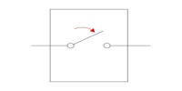 |
| Form B | SPST with NC default state | 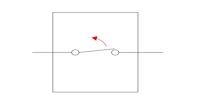 |
| Form C | SPDT with double contact terminals (NO and NC) | 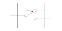 |
| Form D | Similar to Form C, but it closes the next circuit before breaking (opening) the first circuit. | 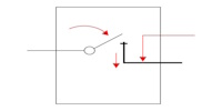 |
Applications
- Relays provide isolation between low-voltage and high-voltage circuits.
- They are used to control multiple circuits simultaneously.
- Relays can function as automatic changeover switches to transfer loads between circuits.
- Microprocessors use relays to control heavy electrical loads.
- Overload relays are implemented to protect motors from overload and electrical faults.
FAQs
What are relays used for?
Relays switch circuits on/off using a low-power signal to control a higher-power circuit, providing isolation between the two.
What is the difference between a latching and a non-latching relay?
A latching relay maintains its contact position after removing the actuation energy, while a non-latching relay requires constant actuation energy to remain in its energized state.
What is the difference between a reed relay and an electromagnetic relay?
Reed relays use magnetic reeds for switching; they're smaller and faster, while electromagnetic relays use coils and armatures and can handle more power.
What is a small signal relay?
A small signal relay is designed to switch low-power electronic signals with high precision and fast response times.
