


What Is a Multi-Position Pneumatic Cylinder?
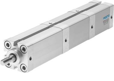
Figure 1: Festo multi-position cylinder
A multi-position pneumatic cylinder can move to several predefined positions, rather than just fully extending and retracting like a standard cylinder. This is achieved by connecting two or more standard cylinders with the same piston diameter in a specific arrangement. The extension and retraction of each cylinder can be controlled to achieve multiple positions. For example, by connecting two cylinders with different stroke lengths, one can configure the system to achieve three or four distinct positions. Multi-position cylinders are economical compared to complex electronic control. Also, manufacturers offer multi-position kits that simplify the assembly process, making it easier to create these custom actuators.
Table of contents
- How multi-position pneumatic cylinders work
- Multi-position cylinder applications
- Selecting standard Festo cylinder types for multi-position applications
- Festo multi-position assembly kits: DPNA, DPNC, DPVU
How multi-position pneumatic cylinders work
Multi-position pneumatic cylinders function by combining two or more standard pneumatic cylinders in a specific arrangement to achieve multiple discrete positions. Here's a brief overview of their operation:
- Configuration: Two or more cylinders with the same piston diameter but different stroke lengths are connected in series. This allows the system to achieve various positions by controlling the extension and retraction of each cylinder.
- Control mechanism: The movement of the cylinders is controlled by a sequence of pneumatic signals that extend or retract the pistons. By selectively activating each cylinder, the system can move to predefined positions.
- Positioning:
- Three positions: Achieved by using two cylinders with the same stroke length. The positions are fully extended, partially extended, and fully retracted.
- Four positions: Achieved by using two cylinders with different stroke lengths. The positions include fully extended, an intermediate position, partially extended, and fully retracted.
- Movement: When one end of the piston rod is stationary, the cylinder barrel moves. This requires flexible pipe connections to accommodate the movement.
- Assembly kits: Manufacturers like Festo offer multi-position assembly kits that simplify the process of configuring standard cylinders into multi-position systems. These kits ensure compatibility and ease of assembly.
For example, Festo multi-position cylinder ADNM connects 2 to 5 cylinders in series with the same piston diameter and different stroke lengths and can achieve up to five positions. They are modular, meaning they can be configured and assembled according to specific requirements.
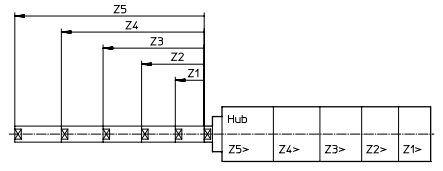
Figure 2: The various positions on a multi-position cylinder (Z1 to Z5).
Multi-position cylinder applications
Multi-position pneumatic cylinders are used in various industrial applications where precise positioning is required. Some common applications include:
- Material handling: For positioning materials at different stages of a process.
- Assembly lines: To move parts to different positions for assembly operations.
- Packaging: For positioning products at different stages of the packaging process.
- Automation systems: Where multiple discrete positions are needed for tasks such as sorting, stacking, or aligning components.
Selecting standard Festo cylinder types for multi-position applications
There are three standard Festo pneumatic cylinder types for multi-position applications:
- ADVU/AEVU: Ideal for compact applications requiring precise positioning and non-rotating motion.
- DSBC: Suitable for heavy-duty applications with long strokes and high forces.
- ADN/AEN: Suitable for compact applications, offering both double-acting and single-acting options.
Consider the following factors while selecting a pneumatic cylinder for multi-position application:
- Piston diameter: All cylinders in the multi-position design must have the same piston diameter. Choose a type that offers the desired diameter range for the design.
- Number of desired positions and stroke lengths: For a higher number of positions (more than 3), choose cylinders with a wider range of available stroke lengths (e.g., DSBC offers strokes up to 2800 mm). ADVU/AEVU and ADN/AEN typically have shorter strokes (up to 500 mm).
- Space constraints: For compact multi-position designs, prioritize compact cylinder types (ADVU/AEVU or ADN/AEN). DSBC cylinders are generally bulkier due to their robust design for heavy-duty applications.
-
Environmental conditions:
- For extreme temperatures (high or low), choose cylinders with heat-resistant or low-temperature seals (available in DSBC and ADN/AEN). ADVU/AEVU typically offer standard seals suitable for moderate environments.
- For high corrosion environments, choose cylinders with high corrosion-resistant features (available in DSBC and ADN/AEN). ADVU/AEVU offer moderate corrosion resistance.
Festo multi-position assembly kits: DPNA, DPNC, DPVU
Figure 3: Festo multi-position assembly kit DPNA
Multi-position assembly kits are designed to connect two pneumatic cylinders back-to-back, allowing for multiple discrete positions within a single assembly. When choosing a connecting piece for the pneumatic cylinder, ensure it is compatible with the cylinder's piston diameter, length, and mounting distance. Each kit allows for a maximum overall stroke length of up to 1000 mm, depending on the cylinder size.
Multi-position kit DPNA for ADN/AEN cylinders
Designed for use with ADN (double-acting) and AEN (single-acting) compact cylinders.
Multi-position kit DPVU for ADVU/AEVU cylinders
Designed for use with ADVU (double-acting) and AEVU (single-acting) compact cylinders.
Multi-position kit DPNC for DSBC cylinders
Designed for use with DSBC standards-based cylinders conforming to ISO 15552.
Example
The multi-position kit DPNC is used to connect DSBC cylinders to create a three- or four-position cylinder. Ensure the cylinders are aligned and have opposite stroke directions. Each DPNC kit includes:
- Flange
- Hex nuts (8x)
- Threaded pins (8x)
- Adhesive (Loctite 243)
However, the kit doesn't include the cylinders, and they should be ordered separately.
Consider using the DPNC kit with three cylinders with different stroke lengths. Ensure these cylinders are of the same type and piston diameter.
- Clean and align: Clean the joint surfaces of each cylinder and align the air connections of the cylinders.
- Apply adhesive and insert the threaded pins: Apply the adhesive (Loctite 243) to the ends of the threaded pins. Screw the threaded pins into the threaded holes of the first cylinder, leaving a bit of projection as specified in Table 1. Projection 't' refers to the specified length by which the threaded pins should protrude from the threaded holes of the pneumatic cylinder to ensure proper assembly and alignment.
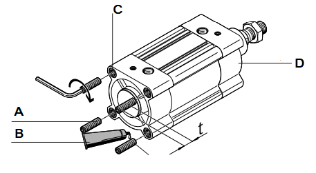
Figure 4: Applying adhesive: threaded pins (A), adhesive (B), threaded holes (C), and pneumatic cylinder (D)
Table 1: DPNC assembly kit projection values for different piston diameters
| DPNC | 32 mm | 40 mm | 50 mm | 63 mm | 80 mm | 100 mm | 125 mm |
| Projection t (mm) | 10.5 | 10.5 | 14 | 13 | 18 | 18 | 20 |
- Attach the flange: Place the flange onto the threaded pins of the first cylinder.
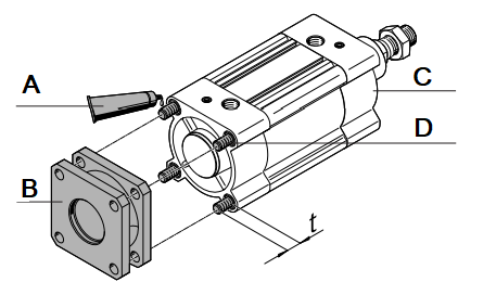
Figure 5: Attaching the flange: adhesive (A), connecting flange (B), pneumatic cylinder (C), and threaded pins attached in their holes (D)
- Tighten hex nuts: Secure the hex nuts onto the threaded pins, tightening them in an alternating order.
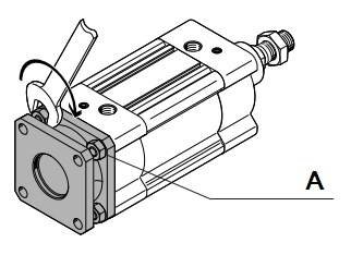
Figure 6: tightening hex nuts (A) on the threaded pins
-
Repeat for additional cylinders:
- Apply adhesive to the ends of the threaded pins of the second cylinder.
- Screw the threaded pins into the threaded holes of the second cylinder, maintaining the projection.
- Place the flange onto the threaded pins of the second cylinder.
- Tighten the hex nuts in an alternating order.
- Repeat the same steps for the third cylinder.
- Final check: Ensure all connections are secure and the cylinders are properly aligned.
