


What Are Limit Switches & How Do They Work
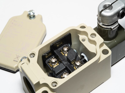
Figure 1: Limit switch sensor
A limit switch is an electromechanical device used to detect the presence or absence of an object by a physical touch. The switch then communicates this through an electrical signal. They are typically used to detect the end travel of an object and ensure operations stay within predefined limits, hence the name limit switch. Limit switches are known for their reliability, simplicity, and durability across industries and residential applications. This article discusses a limit switch's working principle, construction, and main applications.
Table of contents
- What is a limit switch
- How a limit switch works
- Applications
- Limit switch diagram
- Materials
- Micro limit switches
- Advantages and disadvantages
- FAQs
View our online selection of limit switches!

What is a limit switch
A limit switch is an electromechanical device to detect the presence or absence of an object, or to monitor and indicate whether the movement limits of that object have been exceeded. These switches are used in industrial control applications to control machinery and processes, often for safety. The robust exterior casing shields the switch's internal components from external impacts, moisture, oil, dust, and grime, allowing for its use in tough environments.
If you want to learn more about limit switches, read our articles on limit switch types, limit switch maintenance, and limit switch installation.
How a limit switch works
The basic components of a limit switch include an actuator mechanically linked to a set of contacts. When an object comes into contact with the actuator, the device operates the contacts to make or break an electrical connection.
- Physical contact: An object or machine part contacts an actuator on the limit switch.
- Switch activation: This contact mechanically triggers an electrical switch.
- Electrical signal: Depending on its configuration, the switch either opens or closes an electrical circuit.
- Control or indication: This signal controls machinery, provides safety interlocks, or counts objects.
For frequent operation, it is essential that the precision of electrical switches is dependable and their reaction time is quick. Moreover, the electrical capacity of a limit switch should be compatible with the mechanical system loads it will manage to prevent malfunction of the device.
Figure 2: Limit switch symbol
Applications
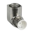
Figure 2: Electronic limit switch
Limit switches are simple, effective and cheap, and come in various forms depending on their application, with different actuator mechanisms such as plungers, roller levers, and rods. They are commonly used in applications like conveyor systems, elevators, and other machinery where it's crucial to detect the position or movement of parts for control purposes.
For example:
- When opening a fridge door, light comes from inside. A limit switch detects whether the door is closed or open.
- In a conveyor system, a limit switch is placed at the end of the travel path to indicate when a product has reached its destination, stopping the conveyor belt to prevent the product from falling off the end.
- In a machine tool, a limit switch might detect the extreme position of a moving component, ensuring that it does not move beyond a certain point and possibly cause damage to the machine or the workpiece.
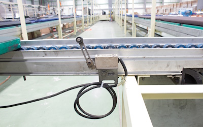
Figure 3: Limit switch in a pneumatic system
Limit switch diagram
Figure 4: Limit switch wiring diagram: limit switch (A), normally closed terminal (B), normally open terminal (C), and common terminal (D)
Figure 4 shows a limit switch's wiring diagram. The resistor is connected in series with the battery's positive terminal and the common terminal of the limit switch. The green color LED's positive terminal is connected to the limit switch's normally open (NO) terminal (Figure 4 labeled A). The red color LED's positive terminal is connected to the NC terminal of the switch.
When the switch is OFF, the normally closed (NC) terminal connects to the common terminal, while the NO terminal is disconnected from the common terminal. Consequently, the red-colored LED receives power and illuminates, while the green-colored LED is powered off.
Conversely, when the switch is in the ON position, the NO terminal connects to the common terminal, while the NC terminal is disconnected from the common terminal. As a result, the green-colored LED receives power and illuminates, while the red-colored LED is powered off.
Materials
A limit switch's construction material varies based on its intended use. For instance, limit switches in elevators are commonly crafted from stainless steel to prevent rusting when subjected to moisture from the air in confined areas such as elevator shafts or the spaces between floors. In industrial settings where exposure to hazardous chemicals is possible, limit switches might also be made from stainless steel but with copper contacts rather than silver because copper is more resistant to corrosion than silver when in contact with such chemicals.
Micro limit switches
The micro limit switch, also known as a micro switch, is a smaller version of a standard limit switch that's used in control circuits. Its compact size makes it suitable for tight or confined spaces where larger switches wouldn't fit. Micro switches typically feature a small actuating plunger that needs to move only a slight distance to initiate the switching action. This plunger is usually located at the top of the switch and must be pressed to a specific extent to activate it. These switches can be equipped with various actuator arms and are commonly rated for electrical capacities of around 250 volts of alternating current and 10 to 15 amperes.
Advantages and disadvantages
Advantages
- Rugged design suitable for industrial environments
- Low power consumption
- Easy to install
- They usually feature robust electrical contacts, which allow them to directly switch higher currents without the necessity of employing an additional relay for control purposes.
Disadvantages
Limit switches come with certain constraints that make them unsuitable for some uses:
- Since their operation is mechanical, they're typically chosen for machinery that functions at lower speeds.
- As contact sensors, they require direct interaction with the object to work.
- The mechanical aspects of their construction are prone to wear and tear or fatigue as time passes, necessitating their replacement eventually.
FAQs
What is the purpose of a limit switch?
The purpose of a limit switch is to regulate machinery, acting as a safety mechanism by controlling an electrical circuit when a set limit is reached.
What is the difference between a limit switch and a proximity sensor?
A proximity sensor detects the presence of an object using electromagnetic fields, light, or sound, while a limit switch is a mechanical device that requires physical contact with an object to operate.

