


JIC Fittings and The SAE J514 Standard
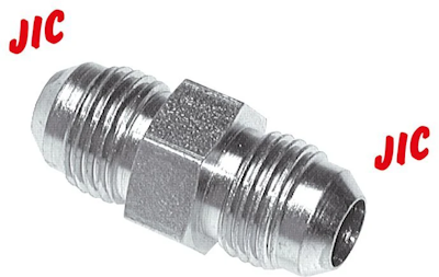
Figure 1: A JIC fitting
JIC fittings are flare fittings characterized by straight threads and are mainly used for hydraulic applications up to 310 bar (4500 psi). They have a 37𐩑 flare seating surface with male and female components. JIC (Joint Industry Council) fittings are typically used in agriculture, construction, and automotive industries. This article discusses the design, installation, and size charts of JIC fittings and briefly reviews the SAE J514 standard.
Table of contents
- Design
- How to identify JIC fitting thread sizes
- JIC fitting dimension chart
- How to install a JIC fitting
- Advantages of JIC fittings
- JIC disadvantages
- SAE J514 standard
- FAQs
View our online selection of threaded fittings!
Design
JIC fittings have a 37𐩑 flare. The male JIC fitting connects to a 37𐩑 flared tube or a female flare fitting. This compact design requires less force to assemble. It can withstand high temperatures and pressures, making JIC fittings a reliable choice for various applications.
Flare fittings are compression fittings used with flared tubing to create a leak-resistant seal. They are secured with a sleeve and nut, ensuring a tight connection. The tip of the flare fitting is engineered to precise angles, adhering to specific industry standards.
This design creates a secure seal through metal-to-metal contact between the fitting nose and the flared tubing. The sleeve supports this connection by distributing compression during assembly. This design eliminates the need for o-rings or tapered threads.
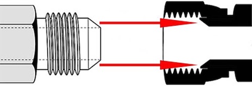
Figure 2: An example of connecting a male and a female JIC fitting. The male 37𐩑 flare matches up with the female flare to provide a tight metal to metal seal.
Configurations
JIC fittings are available in various configurations:
- Reducing: A reducing fitting connects pipes or components of different sizes, allowing for a transition between different diameters.
- Adjustable: Adjustable fittings have a lock nut that provides tighter, more secure sealing.
- Hydraulic: A hydraulic fitting is used to connect components in hydraulic systems.
How to identify JIC fitting thread sizes
The thread size and pitch specify JIC fitting sizes. For example, 'UNF 7/16-20' means the fitting has a Unified National Fine (UNF) thread with a nominal diameter of 7/16 inch and 20 threads per inch. In a JIC fitting measurement, a 'Thread (smaller)' size like 1/8 or 1/4 inch indicates the nominal size of the smaller connection point on a reducing fitting.
JIC fitting dimension chart
Table 1 describes standardized JIC fitting specifications for fluid power systems. Consider connecting a 3/8" hydraulic line to a valve. To select a proper JIC fitting:
- Locate the tube size in the table: 3/8" (10 mm).
- This corresponds to a dash size of -6. The dash size for JIC fittings refers to the tube size in sixteenths of an inch. For example, dash size -4 = 4/16" = 1/4" tube.
- The thread size will be 9/16-18 (9/16" diameter with 18 threads per inch)
- The FFWR (Flats From Wrench Resistance) information is critical for proper installation:
- For a tube connection: 2 flats
- For a swivel nut/hose connection: 1 1/2 flats
When installing, first thread the fitting by hand until it is finger-tight, reaching the "wrench resistance" point. From there:
- For a tube fitting, tighten an additional 2 flats (1/3 of a complete turn, as a hex nut has 6 flats).
- For a swivel nut or hose end, tighten an additional 1 1/2 flats (1/4 of a complete turn).
Table 1: JIC fitting sizes chart
| Tube outer diameter (inch) | Tube outer diameter (mm) | SAE dash size | Thread size/Threads per inch | Tube connection FFWR | Swivel nut or hose connections FFWR |
| 1/8 | - | -2 | 5/16-24 | - | - |
| 3/16 | - | -3 | 3/8-24 | - | - |
| 1/4 | 6 | -4 | 7/16-20 | 2 1/2 | 2 |
| 5/16 | 8 | -5 | 1/2-20 | 2 | 2 |
| 3/8 | 10 | -6 | 9/16-18 | 2 | 1 1/2 |
| 1/2 | 12 | -8 | 3/4-16 | 2 | 1 1/2 |
| 5/8 | 14, 15, 16 | -10 | 7/8-14 | 1 1/2 | 1 1/2 |
| 3/4 | 18 | -12 | 1 1/16-12 | 1 1/2 | 1 1/4 |
| 7/8 | 22 | -14 | 1 3/16-12 | 1 1/2 | 1 1/4 |
| 1 | 25 | -16 | 1 5/16-12 | 1 1/2 | 1 |
| 1 1/4 | 28, 30, 32 | -20 | 1 5/8-12 | 1 | 1 |
| 1 1/2 | 35, 38 | -24 | 1 7/8-12 | 1 | 1 |
| 2 | 42, 50 | -32 | 2 1/2-12 | 1 | 1 |
| 2 1/2 | - | -40 | 3-12 | 1 | 1 |
How to install a JIC fitting
There are three steps to installing JIC fittings.
- Cut the tube: Cut and debur the tube as needed. Read our article on tube cutters for more information.
- Flaring: Use a hydraulic flaring tool to create uniform flares on the tube.
-
Installation:The recommended installation method for JIC fittings is the 'Flats From Wrench Resistance' technique. This ensures sufficient torque without damaging the fitting or threads. Here’s how to properly tighten JIC hose fittings:
- Align and tighten: Align the flared tube with the male and female connectors. Use a wrench to pull until you feel slight resistance, approximately 3.39 Nm (30 in.lb). This is the 'wrench resistance' position.
- Mark the position: Mark this position on male and female connections.
- Further tightening: Tighten the nut further from the wrench resistance position by the number of flats specified in the JIC fittings chart. A flat is one side of a hexagonal nut, equal to 1/6 of a turn.
- Mark again: After tightening the nut to the required number of flats, mark both the female and male connections. This serves as a reference to check tightness over time and aids in reconnecting after maintenance.
Advantages of JIC fittings
- Universal compatibility: JIC fittings adapt to imperial and metric systems, making them widely accepted globally.
- Adaptability: They integrate seamlessly into hydraulic and automotive systems.
- Easily available: JIC fittings are widely available.
- Reliable connectivity: JIC fittings allow easy disconnection and reconnection without leaks.
JIC disadvantages
- High-pressure limitations: JIC fittings may not provide sufficient sealing for demanding applications with vibrations. O-ring sealed fittings are often more suitable in such harsh environments because they provide a tighter seal.
- Specific applications: Because these seals are metal-to-metal, they are limited to hydraulic, liquid, and non-critical applications.
- Fitting deformation: Over-tightening a JIC fitting can deform the nose, reducing the flow diameter. This could reduce the system performance.
SAE J514 standard
The SAE J514 standard is essential for standardizing JIC (Joint Industry Council) fittings, ensuring consistency and interchangeability across manufacturers. Originating from AN (Army-Navy) fittings, JIC fittings were standardized to meet specific requirements for hydraulic systems.
AN fittings are made to stricter military tolerances, while JIC fittings are for commercial use. The SAE J514 ensures that these 37𐩑 flare fittings are reliable and compatible, facilitating their broad application in various hydraulic systems. Read our JIC vs AN fittings article for more details on the differences between both standards.
FAQs
What is a JIC fitting?
A JIC fitting is a hydraulic fitting with a 37-degree flare seating surface, used for high-pressure applications.
How is JIC fitting measured?
Measure the outer diameter and count the threads per inch (TPI) to determine the size.
How does a JIC fitting seal?
A JIC fitting seals through metal-to-metal contact at a 37-degree flare, ensuring a leak-proof connection.
What is the difference between JIC and NPT?
JIC uses a 37-degree flare for sealing, while NPT relies on tapered threads to create a seal.

