How To Wire a Float Switch

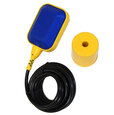
Figure 1: MAC5 float switch
Properly installing and wiring a float switch is crucial to ensure the float switch works correctly to detect the liquid level in a tank. This article discusses how to wire a water tank float switch. However, the same process applies to wiring float switches in other media, such as oil or chemical tanks. Ensuring the correct installation not only prevents potential malfunctions but also enhances the safety and efficiency of the entire system.
Table of contents
View our online selection of float switches!
Float switch operation
A float switch opens or closes an electrical circuit as the liquid level rises or falls. There are three main types of float switches: normally open (NO), normally closed (NC), and changeover contact switches. Here is the difference between them:
-
Normally open (NO) float switch:
- In its default state (when the liquid level does not actuate the float), the electrical circuit is open, meaning no current flows through.
- When the liquid level rises to a certain point, the float actuates and closes the circuit, allowing current to flow.
- Typically used in applications where the user wants to activate a device (like a pump or alarm) when the liquid reaches a certain high level.
-
Normally closed (NC) float switch:
- In its default state (when the liquid level does not actuate the float), the electrical circuit is closed, meaning current flows through.
- When the liquid level rises to a certain point, the float actuates and opens the circuit, stopping the current flow.
- Typically used in applications where you want to deactivate a device when the liquid reaches a certain high level.
-
Changeover contact switch:
- A changeover contact switch, also known as a single-pole double-throw (SPDT) switch, has three terminals: common (COM), normally open (NO), and normally closed (NC).
- In its default state, the common terminal is connected to the normally closed terminal, allowing current to flow through the NC circuit.
- When the liquid level rises to a certain point, the float actuates and switches the connection from the NC terminal to the NO terminal, allowing current to flow through the NO circuit instead.
- This type of switch provides more flexibility and can be used to control two different devices or functions based on the liquid level. For example, it can activate a pump when the liquid level is low and an alarm when the liquid level is high.
The choice between a normally open, normally closed, or changeover contact float switch depends on the application's specific requirements, such as whether a device needs to start or stop when the liquid reaches a certain level, or if multiple actions need to be controlled based on the liquid level.
Float switch installation
Proper installation of a float switch is crucial for its efficient operation. Here’s a simplified guide to installing a float switch:
- Components: A float switch includes a buoyant case, a switch, and an electrical wire. It may also include a float switch diagram to help with wiring.
- Positioning: Attach the float switch to a bracket on the tank wall or along a pipe inside the tank. Ensure the wire is positioned so it doesn’t affect the switch’s depth.
- Counterweight installation: If using a counterweight, make sure there are no obstructions above or below the float switch that could hinder its movement.
- Cable length: The length of the cable between the float switch and the bracket determines how far the float can move, which affects when the pump starts or stops.
MAC float switch wiring
MAC3 and MAC5 float switches are reliable and high-quality float switches. These switches are available for various applications, from clean, non-turbulent water to sewage systems and turbulent water. They come in single or double functions:
- Single function: Single-function float switches are either NC or NO, and they have a common and ground wire.
- Double function: Double-function float switches have an NO, NC, and common wire. Insulate the wire that is not used.
Single-function float switch wiring diagram
Figure 2 demonstrates common wiring diagrams for single-function float switches. The switch's COM terminal connects to the negative terminal of the power source. The switch's NC or NO terminal connects to one terminal on the controlled device (e.g., solenoid valve or motor). And the other device terminal connects to the power supply's positive terminal. There is a ground wire for grounding the switch.

Figure 2: Single-function MAC float switch wiring with emptying (left) and filling (right) applications, respectively.
Double-function wiring diagram
Figure 3 demonstrates common wiring diagrams for double-function float switches. The wiring is similar to the single-function wiring diagram explained above. The primary difference is that double-function float switches do not have a ground wire. Be sure to tape/insulate any wire not being used.

Figure 3: Double-function MAC float switch wiring with emptying (left) and filling (right) applications, respectively.
FAQs
How do you wire a float switch?
To wire a float switch, connect the float switch in series with the device's power supply, ensuring proper voltage and polarity.
What is a float switch used for?
A float switch automatically controls fluid flow based on the liquid level in a tank or reservoir.
Can a float switch directly control a device?
Yes, a float switch can directly control a device by opening or closing the electrical circuit that powers the device.
What precautions should be taken when wiring a float switch?
Ensure correct voltage matching, proper insulation of connections, and adherence to safety standards to prevent electrical hazards.


