


How To Wire a Float Switch To a Solenoid Valve
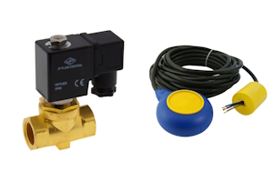
Figure 1: A solenoid valve (left) and float switch (right)
Wiring a solenoid valve with a float switch allows for automated control of liquid levels in various applications. Understanding how to wire a float switch to a solenoid valve is crucial for ensuring the efficient and automated control of liquid levels in various applications. This process involves identifying the key components, determining the desired operation mode (normally open or normally closed), and correctly wiring the float switch to the solenoid valve and power supply. Proper connections and secure wiring are essential to prevent short circuits and ensure reliable operation. By following a systematic approach, including testing and fine-tuning the setup, one can achieve precise control over the solenoid valve's activation based on liquid level changes.
Table of contents
- Steps to connect the solenoid valve to a float switch
- Solenoid valve and float switch wiring diagram
- Common applications
- FAQs
View our online selection of float switches and solenoid valves!
Steps to connect the solenoid valve to a float switch
This section provides an overview of the float switch to solenoid valve connection process. Further information is provided in the next sections.
- Identify the components
- Float switch: Typically has three terminals: common (COM), normally open (NO), and normally closed (NC).
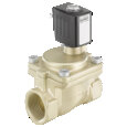
- Solenoid valve: Has two terminals for power connection.
- Power supply: Ensure it matches the voltage and current requirements of the solenoid valve and float switch.
- Determine the desired operation
- Normally open: The solenoid valve is activated when the liquid level changes to a certain point.
- Normally closed: The solenoid valve is deactivated when the liquid level changes to a certain point.
- Wiring the float switch to the solenoid valve
- Power supply connection: Connect one terminal of the power supply to one terminal of the solenoid valve.
- Float switch connection: Connect the other solenoid valve terminal to the float switch's COM or NC terminal (or NO in the case of a NO terminal)
- Closing the circuit: Close the circuit by connecting the other float switch terminal to the power source.
- Secure connections:
- Use wire connectors or terminal blocks to secure the connections.
- Insulate any exposed wires with electrical tape or heat shrink tubing to prevent short circuits.
- Testing:
- Use a multimeter to check the continuity of the connections.
- Power on the system and observe the operation of the solenoid valve as the liquid level changes.
- Adjust the tether length if necessary to fine-tune the activation point of the float switch.
Solenoid valve and float switch wiring diagram
Wiring a solenoid valve to a float switch results in a closed electrical circuit. If only the solenoid valve connects to the power source, in other words both terminals of the power source connect with both terminals of the solenoid valve, the valve will be energized and operate. This is a closed electrical circuit that a float switch can be added to. Instead of connecting both solenoid valve terminals to the power source, one solenoid valve terminal connects to a float switch terminal. Then, the COM terminal on the float switch connects to the power source, completing the circuit.
Figure 2 illustrates how to wire a solenoid valve (Figure 2 labeled S) to a float switch with four types of MAC3 tether float switches. Some float switches are single function (Figure 2 labeled A & B). They are suitable for emptying or filling applications but not both. Also, they have a wire (yellow or green) that connects to ground if necessary. Other float switches are double function (Figure 2 labeled C & D). They are suitable for emptying and filling applications and do not have a wire to ground.
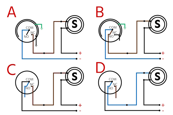
Figure 2: Wiring diagrams for connecting a float switch with a solenoid valve (S). A & B are single function float switches and C & D are double function float switches.
-
Normally open (NO) float switches: Figure 2 B & D are diagrams for normally open float switches, meaning when they change from their normal state, the circuit closes and the solenoid valve is energized. Connect the power supply to the solenoid valve and float switch in the following way:
- Power supply (+) terminal (Figure 2 labeled E) connects to one solenoid valve terminal
- The other solenoid valve terminal connects to float switch NO terminal
- The float switch COM terminal connects to power supply (-) terminal (Figure 2 labeled F)
-
Normally closed (NC) float switches: Figure 2 A & C are diagrams for normally closed float switches, meaning when they change from their normal state, the circuit is opened and the solenoid valve is deenergized. Connect the power supply to the solenoid valve and float switch in the following way:
- Power supply (+) terminal connects to one solenoid valve terminal
- The other solenoid valve terminal connects to float switch NC terminal
- The float switch COM terminal connects to the power supply (-) terminal
- Lines that stop: In the case of lines that connect to one terminal but not another (e.g., Figure 2 labeled C blue line from N.O.), the terminal exists in the float switch but is not necessary for this specific function. Ensure these lines are properly insulated with electrical tape or heat shrinking tubing.
The connection process
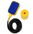
When connecting wires to the float switch, it's not as simple as plugging a wire into the float switch's terminals because they are not accessible. Instead, wires from the power source and solenoid valve get attached to wires coming from the float switch. Typically there are three wires coming from the float switch:
- Single function: COM wire, NC or NO wire, ground wire
- Double function: COM wire, NC wire, and NO wire
Use a multimeter to find the two wires that have continuity when the switch is closed:
- Ensure the float switch is in the closed position
- Connect one multimeter probe to one float switch wire and connect the other multimeter probe to a different float switch wire
- If the multimeter detects continuity, these are the two wires that enter the circuit with the solenoid valve and power source
- If there is no continuity, continue to test two wires at a time until there is continuity
- Double check that there is not continuity when the float switch is in the open position
- Once the two float switch wires with continuity are determined, use wire connectors to attach one wire to the power source and the other to the solenoid valve
- It's common practice to connect the power source load to the float switch. However, the circuit will still work if the float switch connects to the power source's negative terminal.
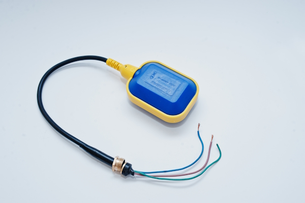
Figure 3: The terminals of a float switch are not directly accessible. Wiring a float switch to a solenoid valve and power source is done by finding the two wires that have continuity.
Common applications
- Water tanks and reservoirs: Automatically controls the filling or emptying of tanks to prevent overflow or dry running of pumps. Ensures efficient water management in various settings.
- Sump pumps: Activates the pump when water levels rise and deactivates it when drained. Prevents flooding and water damage in basements or crawl spaces.
- Aquariums and fish ponds: Maintains optimal water levels for aquatic life. Ensures a stable environment for fish and plants.
- Cooling towers: Adds water when levels drop to maintain efficient cooling. Ensures the cooling system operates effectively.
- Irrigation systems: Supplies water to fields or gardens based on tank levels. Conserves water and ensures optimal irrigation.
- Boilers and heating systems: Adds water to boilers when levels drop. Prevents damage and ensures consistent heating performance.
- Chemical processing plants: Controls liquid levels in tanks and reactors for safety and efficiency. Prevents spills and ensures proper mixing.
- Wastewater treatment plants: Manages tank levels for effective wastewater processing. Prevents overflow and ensures regulatory compliance.
FAQs
How do you wire a float switch to a solenoid valve?
To wire a float switch to a solenoid valve, connect the float switch in series with the solenoid valve's power supply, ensuring proper voltage and polarity.
What is a solenoid valve with a float switch used for?
A solenoid valve with a float switch is used to automatically control fluid flow based on the liquid level in a tank or reservoir.
Can a float switch directly control a solenoid valve?
Yes, a float switch can directly control a solenoid valve by opening or closing the electrical circuit that powers the solenoid valve.
What precautions should be taken when wiring a float switch to a solenoid valve?
Ensure correct voltage matching, proper insulation of connections, and adherence to safety standards to prevent electrical hazards.

