


How Digital Pressure Sensors and Switches Work
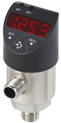
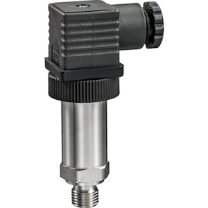
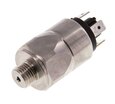
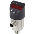
Figure 1: Digital pressure switch (left) and pressure sensor (right)
Digital pressure switches and sensors are integral for monitoring and controlling pressure in various applications, from water systems to pneumatic controls. By converting applied pressure into electrical signals, these devices offer precise measurements, real-time monitoring, and seamless integration with digital control systems. This article explores the working of digital pressure switches and sensors, their components, operating principles, and the advantages they bring to processes that demand accuracy and reliability.
Table of contents
- What are digital pressure sensors and switches?
- How electronic pressure sensors work
- Types of pressure sensors
- Choosing the right sensor technology
- How pressure switches work
View our online selection of pressure switches!
What are digital pressure sensors and switches?
- A pressure sensor, or transducer is a device that measures pressure, typically of gasses or liquids and converts the physical parameter of pressure into an electrical signal.
- A pressure switch is a specific type of pressure sensor that includes an additional mechanical or electronic switch component. A pressure switch makes or breaks an electrical contact when a certain set pressure level is reached.
Digital pressure switches are electronic pressure transmitters with added capabilities. They not only measure pressure but also allow for other features like a digital display and the electronic adjustment of switch points. This dual functionality means that simple control tasks can be executed without the need for separate devices. Users can set and modify switching points with ease, either through a digital display or remotely via an I/O link, enhancing the system's adaptability to different operating conditions.
The next sections discuss the various mechanisms through which the sensor converts the input pressure into an electrical output.
How electronic pressure sensors work
Electronic pressure sensors detect pressure changes and convert them into a proportional electrical signal. There are four main principles by which these sensors operate:
Resistive pressure measurement
Resistive pressure measurement quantifies pressure by detecting changes in electrical resistance caused by the deformation of a material. The resistance of a conductor is affected by its physical dimensions—specifically, its length and cross-sectional area. The electrical resistance of a conductor is determined by the formula:
R=ρ*L/A
- R: Electrical resistance
- ρ: Resistivity
- L: Length
- A: Cross-sectional area
When pressure is applied to a conductor, it can cause the material to stretch or compress. Stretching the conductor increases its length (l) and decreases its cross-sectional area (A), which in turn increases its resistance. Conversely, compression results in a shorter length and a larger cross-sectional area, leading to a decrease in resistance.
Pressure sensors that use this principle usually have a diaphragm on which four metallic strain gauges are placed. They are distributed over the elongation and compression areas. The resistance thus changes according to the deflection (compression or elongation) of the diaphragm. When the diaphragm bends, the strain gauges also change shape:
- If the diaphragm stretches out, the strain gauges on those parts get more resistance
- If the diaphragm gets pushed in, the strain gauges on those parts get less resistance.
These changes in resistance are linked to how much pressure is pushing on the diaphragm. A wheatstone bridge can also be used for more accurate measurements.
Figure 2: Resistive pressure measurement: strain gauges (A), straining (B), compression (C), and applied pressure (D).
Piezo-resistive pressure measurement
A piezoresistive material is a type of material that changes its electrical resistance when mechanical stress is applied to it. This property is known as the piezoresistive effect. This effect is particularly pronounced in semiconductors like silicon, whereas it is relatively minor in conducting metals.
In a piezoresistive pressure sensor, the diaphragm that senses pressure is constructed from a semiconductor material. Strain gauges made of the same semiconductor material are embedded directly into this diaphragm, creating a cohesive sensing unit. These strain gauges are typically arranged in a set of four and are connected to form a Wheatstone bridge, which is used to measure the minute changes in resistance that occur as the diaphragm deforms under pressure.
Advantage
Piezoresistive elements can accurately measure very low pressure ranges, making them ideal for applications where precision is crucial.
Limitations
- Compatibility issues: Semiconductor materials are not universally compatible with all types of fluids they come into contact with. To prevent damage to the sensor, the semiconducting elements are shielded from the media being measured by applying the pressure to a metal membrane that is resistant to the media. The pressure is then transmitted to the semiconductor diaphragm through a stable transmission medium, such as oil, which ensures that the sensitive semiconducting material only comes into contact with a substance it can withstand.
- Sensitivity to temperature: Piezoresistive elements are highly sensitive to temperature fluctuations, which can affect their performance and accuracy.
- Manufacturing consistency: Variations in the manufacturing process can lead to inconsistencies in sensor behavior.
To address these challenges, each piezoresistive pressure sensor must undergo individual temperature compensation to ensure reliable and consistent operation.
Capacitive pressure measurement
Capacitive pressure measurement determines the pressure of a medium by measuring the change in capacitance caused by the deformation of a diaphragm when pressure is applied. A capacitor is an electrical component that stores energy in an electric field between two conductive plates separated by an insulating material (FIgure 3). The capacitance of a dual-plate capacitor is calculated using the following relation:
C=ε*A/d
- C: Capacitance of the dual-plate capacitor
- ε: Permittivity
- d: Plate separation
- A: Cross-sectional area
In a capacitive pressure sensor, the two plates of the capacitor are configured such that one plate is a movable diaphragm that responds to pressure changes, while the other plate remains stationary. When pressure is applied, the diaphragm deflects, altering the distance (d) between the two plates. Since the area of the plates (A) and the permittivity (ε) of the insulating material are constant, any change in the plate separation directly affects the capacitance.
Advantages
- The direct relationship between plate separation and capacitance means that capacitive pressure sensors are highly sensitive to pressure changes. They are particularly well-suited for measuring very low pressure ranges, such as those in the single-digit millibar range.
- The design of these sensors provides a high level of overload protection. The movable diaphragm can flex all the way to the stationary plate without causing damage, which helps to prevent sensor failure in situations where the pressure exceeds the intended measurement range.
- Capacitive pressure sensors are commonly used in applications where precise low-pressure measurements are required, such as in environmental monitoring, medical devices, and HVAC systems. Their high sensitivity and overload protection make them reliable and durable choices for these and other sensitive measurement tasks.
Limitations
- Capacitive sensors can be sensitive to vibrations and may require protection from harsh environments.
- Capacitive sensors may be affected by changes in the dielectric constant of the medium between the plates, which can be influenced by factors like humidity and temperature.
Figure 3: Capacitive pressure measurement: fixed plate (P1), applied pressure (P), moving plate (P2), area of cross section (A), distance between plates (d), and permittivity (ε)
Piezo-electric pressure measurement
Piezoelectric pressure measurement refers to the use of piezoelectric materials to measure pressure changes. Piezoelectric materials have the unique property of generating an electric charge in response to applied mechanical stress. This phenomenon is known as the piezoelectric effect.
Certain crystalline materials, like quartz, tourmaline, and certain ceramics, exhibit piezoelectric properties. The crystal's structure is such that when it is deformed by the applied force, the lattice elements within the crystal—which are electrically charged—become displaced. This displacement leads to the generation of an electric dipole moment within the crystal, which in turn causes opposite surfaces of the crystal to acquire positive and negative charges.
This causes a voltage difference across the crystal that can be measured. This voltage is directly proportional to the applied mechanical stress, allowing the pressure to be determined from the voltage output of the sensor.
Advantages
- No external power required: Piezoelectric materials generate their own electric charge in response to pressure, so they do not need an external power source.
- Wide dynamic range: Piezoelectric sensors can measure a broad range of pressures, from very low to very high.
Limitations
Piezoelectric sensors are not suitable for measuring static pressure because the generated charge can dissipate over time. Also, the electrical charge produced by the piezoelectric effect can leak away, especially at high temperatures, which can affect accuracy.
Due to this limitation, piezoelectric pressure sensors are typically used in applications where pressure changes rapidly, such as in the detection of sound waves, monitoring of engine combustion processes, or measurement of blast pressures.
Types of pressure sensors
The principles of pressure measurement discussed earlier are available in three main types of sensors: ceramic thick-film sensors, metal thin-film sensors, and piezoresistive pressure sensors.
Metal thin-film sensor
Metal thin-film sensors are constructed with both the diaphragm and the main housing made of stainless steel, which provides excellent durability and resistance to corrosive media. The strain gauges, along with insulation layers, conducting paths, and compensating resistors, are applied to the side of the diaphragm that does not come into contact with the medium being measured. This ensures that the sensitive components are protected from the environment.
Features
- Metal thin-film sensors are typically manufactured in cleanroom conditions, and sometimes even under vacuum, to ensure the highest quality and to prevent contamination.
- Metal thin-film sensors are very stable and resistant to shock and vibration, which makes them well-suited for applications involving dynamic loads.
- They can be directly welded onto a system connection, eliminating the need for separate sealing materials. This can simplify installation and enhance the integrity of the sensor connection.
- The ductility of steel allows for a certain degree of deformation without failure; these sensors generally have a lower overpressure range (pressure that exceeds the designed operating pressure range). However, they can withstand very high burst pressures, ensuring safety in applications where sudden pressure spikes may occur.
Ceramic thick-film sensor
Ceramic thick-film sensors have the main body and the diaphragm made of ceramic, typically aluminum oxide (Al2O3), which is chosen for its processability and stability. The strain gauges are applied to the side of the ceramic diaphragm that does not come into contact with the medium being measured. These gauges are made from a special paste that is applied in a thick layer—hence the term "thick-film." The paste is then burned into the diaphragm at high temperatures and subsequently covered with a protective coating to ensure durability.
- Manufacturing of ceramic thick-film sensors takes place in cleanroom conditions to prevent contamination. Ceramic materials are highly resistant to corrosion, making these sensors suitable for use in harsh chemical environments.
- The additional seal required for the sensor assembly may not be resistant to all media.
- Ceramic is also a brittle material, which means that while these sensors can withstand significant pressure, they may have a lower burst pressure compared to metal thin-film sensors.
Piezoresistive sensor
Piezoresistive sensors are more complex in their construction than ceramic thick-film or metal thin-film sensors. The core of a piezoresistive sensor is a silicon chip that houses the diaphragm with embedded piezoresistive resistors. These chips are much smaller in surface area compared to the diaphragms used in thick or thin-film sensors, often just a few square millimeters in size.
Due to their sensitivity to environmental factors, piezoresistive chips must be protected. This is achieved by encasing the chip in a stainless steel housing, which is sealed with a thin stainless steel diaphragm (Figure 4 labeled E). The space within the housing is filled with a transmission fluid (Figure 4 labeled F) that conveys the pressure from the outer diaphragm to the sensor diaphragm. Special displacement bodies (Figure 4 labeled C) minimize the effects of thermal expansion of the transmission fluid on the measurement accuracy.
The sensor chip is mounted and electrically connected using a header (Figure 4 labeled B), which can be hermetically welded to the housing. Bond wires (Figure 4 labeled H) connect the sensor to external pins (Figure 4 labeled A). A ventilation tube (Figure 4 labeled G) is positioned in the center of the header, leading to the backside of the sensor diaphragm. This tube allows for the measurement of absolute pressure when the chamber behind the sensor is evacuated and the tube is sealed. If the ventilation tube is open, the sensor measures relative pressure, with the tube connecting to the environment either through the outer casing or a ventilated cable. It is crucial to protect the ventilation tube from contamination and moisture to maintain sensor accuracy.
Figure 4: Piezoresistive sensor construction: pin (A), header (B), displacement body (C), piezo chip/sensor (D), diaphragm (E), transmission fluid (F), ventilation tube (G), and bond wires (H)
Choosing the right sensor technology
Table 1: Different measurement applications with sensor technologies
Requirement |
Sensor principle |
||
| Metal thin-film sensor | Ceramic thick-film | Piezo-resistive | |
| Absolute pressure measurement | Not suitable | Partially fulfilled | Good |
| Very low pressure ranges | Not suitable | Not suitable | Good |
| Very high pressure ranges | Good | Not suitable | Not suitable |
| Shock and vibration resistance | Good | Partially fulfilled | Partially fulfilled |
| Long-term stability | Good | Partially fulfilled | Good |
How pressure switches work
A pressure switch is essentially a pressure sensor that incorporates an additional component—a mechanical or electronic switch. This integration enables the device not only to measure pressure but also to act upon the measured value by opening or closing an electrical circuit once the pressure reaches a predetermined threshold.
- Mechanical switches: In a mechanical pressure switch, the pressure measurement component (the sensor) directly acts on a mechanical switch. When the pressure reaches a certain level, it causes a physical movement (such as the bending of a diaphragm or a piston movement) that mechanically triggers a switch to open or close an electrical circuit. This action can turn a system on or off, activate alarms, or initiate other mechanical processes.
- Electronic switches: Electronic pressure switches incorporate a pressure sensor that converts pressure into an electrical signal. This signal is then processed by electronic circuitry that determines whether the pressure is above or below a user-defined threshold. If the threshold is crossed, the electronic circuit activates a relay or a transistor switch, thereby opening or closing an electrical circuit. This type of switch offers greater flexibility and precision, as the threshold can be easily adjusted through software, and the switch can be designed to trigger various electronic actions.


