


Camlock Fittings - Overview and Types
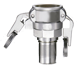
Figure 1: Camlock fitting
A camlock fitting is a quick-connect coupling that efficiently and securely connects or disconnects hoses and pipes. It is easy and quick to use, requiring no tools. Camlock fittings, also called cam and groove couplings, are used in manufacturing, agriculture, oil, gas, chemical, pharmaceutical, and military applications. They are perfect for dirty environments and well suited for frequent hose changes, such as petroleum and industrial chemical trucks.
Table of contents
- How do camlock fittings work?
- Why use camlocks?
- Camlock fitting types
- Size
- Materials
- Temperature
- Pressure
- Camlock standards
- Accessories
- Maintenance
- FAQs
View our online selection of Camlock fittings!
How do camlock fittings work?
The assembly of a camlock coupling consists of two primary components: the male camlock adapter and the female coupler. The coupling requires two parts: the camlock socket (female) and the plug or adapter (male part). They facilitate quick and secure connections without any tools in fluid transfer systems.
- To assemble the coupling, begin by extending the handles of the female coupler outward. Then, insert the male adapter into the female coupler, ensuring proper alignment (Figure 2 labeled A).
- Once the male adapter is inserted, close both cam arms simultaneously (Figure 2 labeled B). This action locks the two halves together, ensuring that the grooved adapter is securely seated against the gasket within the coupler.
- Before disconnecting the camlock coupling, fully depressurize the system to prevent accidental fluid discharge and potential injury or equipment damage. Once depressurized, open the cam arms and remove the male adapter from the coupler.
Verifying that the adapter and coupler match the sizes and materials (discussed later) is crucial to preventing compatibility issues and ensuring optimal performance.
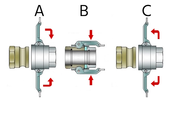
Figure 2: Connecting a Camlock coupling with a plug: connection (A), assembly lock (B), disconnection (C).
Why use camlocks?
Camlock couplings offer several advantages that make them a preferred choice in various industrial applications:
- Ease of use: Camlocks can be connected by hand without needing tools, making assembly easy and user-friendly.
- Quick to couple: Connections can be made in seconds, as no threads are involved when joining the male and female coupler halves. This speed is crucial in operations requiring frequent connections and disconnections.
- Versatile: Suitable for most liquid, powder, and gas applications. However, they are not recommended for compressed air applications due to safety concerns.
- Durable: The simple design of camlocks minimizes issues with dirt and reduces the risk of premature damage from wear and tear, ensuring longevity.
- Reliable: Designed for multiple repeatable uses, camlocks maintain functionality over the product's lifespan, consistently providing secure connections.
- Cost-effective: Compared to other quick disconnects, camlocks are budget-friendly.
Camlock fitting types
Camlock connectors come in various types to accommodate different connection needs and applications. For example:
- A Type A Camlock connector features a male adapter (the camlock part) on one end and a female thread on the other. This makes them ideal for connecting to tanks or equipment with female-threaded ports.
- Type C connectors feature a female coupler with a hose barb, which is perfect for quickly attaching hoses in fluid transfer applications.
Read our camlock coupling types article for more information on the features of each camlock type.
To select the right type, determine the camlock and thread portions, identifying whether each is male or female.
- For instance, a female cam is required to connect to a male camlock. Similarly, a male thread is needed if the thread portion must connect to a female thread. In this case, a female camlock x male thread is necessary, corresponding to a Type B coupling.
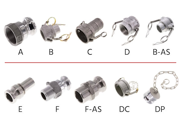
Figure 3: Various types of camlock couplings
Size
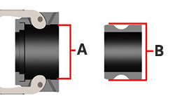
Figure 4: Camlock coupling sizes: Female couplers are measured on the inside (A), while male plugs are measured on the outside (B).
Camlock coupling sizes are determined by their nominal size, where the male and female couplings have slightly different sizes for coupling purposes. The male plug (Figure 4 labeled B) is measured on the outside, while the female coupler is measured on the inside (Figure 4 labeled A). Read our camlock fitting measurement article for more details on measuring camlock fittings and our comprehensive guide on camlock fitting charts.
Materials
Camlock fittings are available in various materials, each providing unique properties tailored to specific applications and industry needs.
- Stainless steel is well-suited for long-term use in high-pressure environments.
- Brass offers durability and good corrosion resistance at a lower cost than stainless steel.
- Aluminum is lightweight, economical, and strong.
- Plastics like polypropylene are lightweight and resistant to various chemicals, suitable for corrosive substances and low-pressure environments.
Read our camlock coupling materials article for a comprehensive guide on the features and applications of different camlock materials.
Temperature
The seal material primarily determines the temperature rating of a Camlock coupling. While the metal components of the coupling are generally more heat-resistant and capable of withstanding higher temperatures, the gaskets are the limiting factor. Common seal materials for Camlock couplings include NBR and EPDM, which can operate at temperatures up to 80 𐩑C (176 𐩑F). To learn more about the chemical properties of various materials, read our article on the chemical resistance of materials.
Pressure
The coupling material and operating temperature mainly determine the working pressure of a camlock coupling. Aluminum and plastic are generally unsuitable for high-pressure applications, whereas stainless steel can effectively endure high pressures. Always ensure the selected camlock can withstand the application pressure.
Camlock standards
- A-A-59326D (formerly Mil-C-27487): This U.S. military specification for camlock couplings ensures that couplings of the same design are interchangeable. It includes guidelines for casting processes, materials, dimensions, tolerances, pressure ratings, and inspection procedures. However, it standardizes only the coupling side and does not cover components such as levers, bolts, rings, and seals.
- EN 14420-7: Ratified in September 2004, this European standard was developed to overcome the limitations of the American standard by standardizing additional components. It features a flat thread seal for female threaded parts and a smooth hose shank designed for use with safety clamps.
Interchangeability
Camlock couplings are typically interchangeable between manufacturers, except for the 12”, 5”, and 8” sizes. The A-A-59326A specification does not cover 5” and 8” cam and groove couplings. Additionally, there are differences between couplings made to the EN 14420-7 standard and those made to the original MIL-C-27487 standard, especially regarding hose tail design, thread specifications, and part numbers.
Accessories
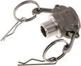
R clips
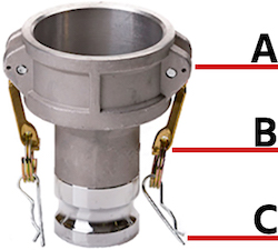
Figure 5: Camlock couplings with safety levers are sometimes fitted with an additional r-clip for safety. The clip (A) can be fitted into the hole in the coupling (C) when the levers (B) have been fastened and the coupling is connected.
The R clips in camlock couplings prevent accidental disconnection of the coupling assembly. The R clip (Figure 5 labeled A) can be pushed through a hole (Figure 5 labeled C) behind the handle (Figure 5 labeled B). This prevents the handle from becoming loose once the plug is connected to the coupling. R clips serve as a safety feature to ensure that the two halves of a camlock coupling do not catch on anything or become loose.
Lock system
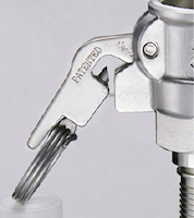
Figure 6: Camlock safety lock
Automatic locking arms in camlock couplings prevent unintentional disconnection and potential spillage. A locking camlock fitting is vital when handling highly flammable or toxic liquid chemicals.
Seals
Replacement seals for camlock couplings are crucial for maintaining leak-proof connections. Available in materials like EPDM, Viton, Buna-N, and PTFE, the camlock gaskets offer different resistances to heat, chemicals, and oils.
- EPDM: Excellent resistance to heat, weather, and ozone, with a maximum temperature of 130 𐩑C (266 𐩑F), making it ideal for outdoor and high-temperature applications.
- Viton (FKM): Offers superior chemical resistance, particularly to acids and fuels, with a maximum temperature of 180 𐩑C (356𐩑 F), suitable for harsh chemical environments.
- Buna-N (Nitrile, NBR): Known for its excellent oil and fuel resistance, with a maximum temperature of 80 𐩑C (176 𐩑F), making it perfect for petroleum-based applications.
- PTFE (Teflon): Provides outstanding chemical and temperature resistance, with a maximum temperature of 200 𐩑C (392 𐩑F), ideal for highly corrosive or extreme temperatures.
Read our gasket selection article for more information on choosing a sealing gasket for an application.
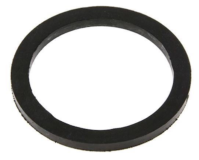
Figure 7: EPDM seal
Coupling chain
A Camlock coupling chain attaches dust caps and plugs to camlock couplings, preventing their loss and ensuring they are always available when needed. This is particularly useful in industries like agriculture, manufacturing, and chemical processing, where maintaining clean and secure connections is crucial. These chains are designed for easy installation, allowing for quick attachment and removal, which reduces downtime.
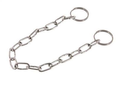
Figure 8: Camlock coupling chain
Maintenance
When using Camlock couplings in industrial applications, following best practices to ensure optimal performance and longevity is essential. Here are some key considerations:
- Cleanliness: To prevent leaks and contamination, ensure all components are free from dirt and debris before connecting.
- Regular inspection: Implement a routine maintenance schedule to inspect Camlock couplings frequently. Check for wear or damage, especially on gaskets, cam bodies, and lever arms. Replace any worn parts immediately, as moving parts are subject to wear and tear.
- Pressure and temperature limits: Set specified limits to prevent coupling failure and safety hazards.
- Gentle handling: Avoid excessive force; ensure proper alignment and cleanliness for smooth connections.
FAQs
What is the use of a camlock hose fitting?
A camlock hose coupling is a quick-connect coupling used to join hoses and pipes securely. It locks cam arms over a male adapter, ensuring a tight seal without tools.
What are camlock fittings used for?
Camlock fittings enable quick, secure hose and pipe connections in agriculture, manufacturing, and chemical processing industries. They efficiently transfer liquids, powders, and other materials.
What are stainless camlock fittings?
Stainless camlock fittings are durable, corrosion-resistant couplings made from stainless steel. They are ideal for harsh environments and applications requiring high hygiene standards.
What are aluminum camlock fittings?
Aluminum camlock fittings are lightweight, cost-effective couplings made from aluminum, suitable for general-purpose applications and less corrosive environments.


