


A Complete Rolling Bearing Guide
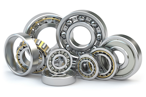
Figure 1: Bearings
Bearings are mechanical parts that assist in the rotation of an object, support loads, and reduce friction between moving parts. They are available in a wide variety of designs, each with its own characteristics making them suitable for specific applications. One of the most common rolling bearing applications is to support a shaft that rotates inside a machinery part. Nearly every application that has rotation to operate uses bearings in one way or another, from cars, planes, electric generators, turbines, to medical equipment and watches. This article explores the various types of rolling bearings most common in the marketplace.
Table of contents
- Bearing basics
- Loads
- Ball bearings
- Roller bearings
- Special bearing designations
- Bearings selection criteria
View our online selection of bearings!
Bearing basics
A rolling bearing is used for rotational applications to either transfer loads between machine components or to guide machine elements like wheels, axles, and shafts. They offer low friction, are highly precise, and are capable of high rotational speeds with low noise, heat, and energy consumption. Bearings are cost-effective, interchangeable, and adhere to international standards of dimension.
Rolling bearings and ball bearings
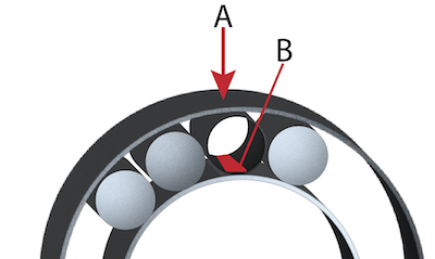
Figure 2: Due to loads pressing on the rolling bearing (A), the contact line (B) on the inner raceway will deform to a more rectangular shape. For ball bearings this contact point would become more elliptical.
Rolling bearings can be classified into two basic categories based on the rolling elements they contain. The main difference lies the contact between the rolling elements and the raceways.
- Ball bearing: A ball bearing consists of balls that make a contact point with ring raceways. As the load on the bearing increases, it causes the contact area of the bearing to become elliptical. Ball bearings can accommodate high rotational speeds due to their small contact areas, but their capacity to carry load suffers due to their design.
- Rolling bearing: In rolling bearings, the rollers make a contact line with the ring raceways. Increased loads cause the contact line to become more rectangular (Figure 2). Because of this larger contact area, it can accommodate heavier loads but rotates at a slower speed than a ball bearing of similar size.
Bearing parts
A rolling bearing consists of 4 main components as seen in Figure 3:
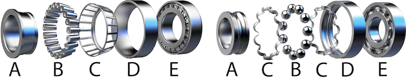
Figure 3: The basic design of a roller bearing (left) and ball bearing (right) are: inner ring & raceway (A), rolling elements (B), cage (C), outer ring & raceway (D), and the complete bearing (E).
-
Inner ring and raceway (A): The inner raceway is a smaller ring over the shaft. It is positioned inside the outer raceway (D).
- On roller bearings, the raceway is flat or tapered with a flange that holds the rollers in place.
- On ball bearings, a groove is cut into its outer circumference.
- Rolling elements (B): Bearings can rotate freely due to the balls or rollers fixed between the inner and outer races. If they weren't there, friction between the races would quickly destroy the bearing. Balls and rollers in bearings are manufactured to exact symmetrical specifications, as an asymmetrical rolling element reduces the bearing's performance. Rolling elements are highly dependent on their surface quality since it affects how smoothly they can rotate. Friction generates heat, shortening the bearing life and increasing bearing noise.
- Bearing cage (C): A bearing cage holds the balls or rollers in place in between the inner and outer raceway. This ensures that the balls/rollers can rotate freely, but they retain their spacing.
-
Outer raceway (D): Bearings consist of an outer raceway and an inner raceway (ring) that houses the balls or rollers inside.
- On roller bearings, the outer raceway is flat, spherical, or tapered with a flange that holds the rollers in place.
- On ball bearings, a groove is cut along the inner circumference of the raceway so that the balls will be held in place.
- Complete bearing (E): When all of the components are assembled, they make up the bearing. The rolling elements can be exposed, and these require proper lubrication to function properly. Bearings can come with seals, which protect the rolling elements from the environment and are already lubricated. Learn more about bearing lubrication.
Loads
When discussing bearings, it is important to discuss loads. A load is the force acting on the bearing. A loaded bearing, has forces acting on it currently while an unloaded bearing does not. Various load factors need to be considered, such as the load direction, load type, and load condition.
Load direction
- Radial Load: Radial load is any load acting at right angles to the bearing axis (Figure 4 left).
- Axial load: Axial or thrust load is any load acting along the bearing axis (Figure 4 middle).
- Combined load: Combined load is a combination of radial and axial load components (Figure 4 right).
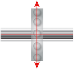
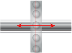
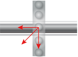
Figure 4: Radial load (left), axial or thrust load (middle), and combined load (right).
Load type
- Dynamic loads: These are the rotational forces acting upon the bearing when spinning. These loads cause the bearing to wear.
- Static loads: A continuous high or intermittent peak load. Under static loads, the bearing's material strength is the limiting factor.
Load condition
- Constant load: Under constant load, the load direction does not change and the same part of the bearing is constantly subjected to the load, also known as the loaded zone.
- Alternating load:Under alternating loads, zones adjacent to each other in the bearing alternately become loaded and unloaded.
Ball bearings
Ball bearings consist of different categories of ball-type bearings.
Deep groove ball bearings
Deep groove ball bearings have their balls held into place by deep grooves on the raceways and can accommodate both radial and axial loads. They are suitable for very high rotational speeds, offer low friction, create minimal noise and vibrations, are easy to install, and require less maintenance than other types of bearings.
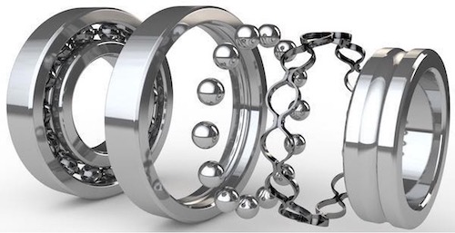
Figure 5: This image shows the various parts of deep groove ball bearings. The deep groove raceway can be seen outside of the inner ring, shown on the far right.
Angular contact ball bearings
The inner and outer ring raceways of these bearings are offset from each other, as seen in Figure 6. As a result, these bearings are designed to support both radial and axial loads simultaneously. In addition, the bearing's axial load capacity increases as the contact angle increases. Angular contact ball bearings should be used for high precision, high speeds, and axial loads, which can be found in gearboxes, pumps, and machine tool applications.
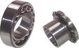
Single row angular contact ball bearings
These handle axial loads in only one direction, which is why single row angular contact ball bearings are commonly installed by putting two single row angular contact ball bearings back-to-back, face-to-face, or in tandem. Therefore, multiple directional forces can be accommodated. Bearings are locked into place with the help of a locking collar, to prevent sliding along the axle.
- Back-to-back: By mounting the bearings in this manner, they can accommodate both radial and axial loads in any direction. Because the distance between the bearing center and loading point is larger than other mounting methods, it can handle large momentary and alternating load forces.
- Face-to-face: Through this mounting sequence the bearing can handle radial and axial loads in either direction. However, because the distance between the bearing center and loading point is smaller through this mount, momentary and alternating force capacity is lower.
- Tandem: A tandem mount can accommodate single direction axial loads as well as radial loads. Because the loads on the axis are received by both bearings it can handle heavy axial loads.
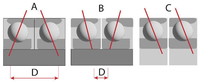
Figure 6: Single row angular contact bearing mounting methods: back-to-back (A), face-to-face (B), tandem (C) and the distance between the bearing center and loading point (D).
Double row angular contact ball bearings
The double row arrangement of angular contact ball bearings is similar to two single row angular contact ball bearings put back-to-back, but requires less axial space. In addition to radial and axial loads, they are also capable of absorbing tilting moments.
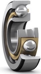
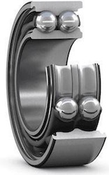
Figure 7: Single angular ball bearing (left) and double angular ball bearing (right)
Self-aligning ball bearings
Self-aligning ball bearings are used when an application is likely to suffer from misalignment or shaft deflection. It has two rows of balls that share the outer, spherical raceway, while the inner ring has two angular contact deep groove raceways. Because the balls are held in place in the inner raceway, but have some freedom of movement on the outer raceway, the bearing is able to operate even when it is out of alignment with the shaft. However, they cannot accommodate high load applications.
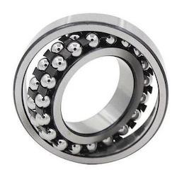
Figure 8: Self-aligning ball bearing
Thrust ball bearings
Thrust ball bearings are used for axial loads. There are two key designs available: single-direction and double-direction.
- Single direction thrust ball bearings consist of two rings, referred to as shaft and housing washers, and a single ball and cage assembly. They can only handle axial loads in one direction, depending on the placement of the flange on the inner, outer, or both raceways.
- Double direction thrust ball bearings consist of three washers and two ball and cage assemblies. The shaft washer separates the ball and cage assemblies. These bearings have been designed to be used with axial loads, and are not suitable for radial loads. They can handle axial loads in both directions.
Read our ball bearing guide for more information.
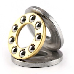
Figure 9: Single thrust ball bearing with the housing and shaft washers, and ball and cage assembly.
Roller bearings
Within the roller bearings category, they are further categorized which we cover in the next sections.
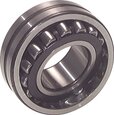
Spherical roller bearings
Spherical roller bearings are used for heavy radial and axial loads. Two main designs are available: single row and double row spherical roller bearings. These bearings get their name from the spherical shape of the outer raceway and the spherical shape of the rollers.
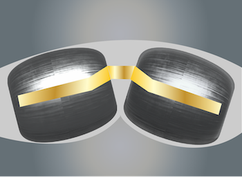
Figure 10: A double row spherical roller bearing (left) has a spherical raceway on the outer ring, and a double grooved angular raceway on the inside ring with a cage that holds bearings in place. A single row spherical roller bearing (right) has a spherical raceway on both rings.
These bearings are especially suited for applications prone to misalignment or shaft deflections. Due to their high load capacity and their ability to accommodate misalignment, they have a low maintenance cost and typically a longer bearing service life. These bearings are used on conveyors, bridges and cranes, paper mills and gearboxes, etc.
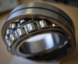
Figure 11: Double row spherical roller bearing
Cylindrical roller bearings
Cylindrical roller bearings are used for high-speed and heavy radial load application. In addition to being ground to ensure maximum contact with the raceway, their rolling elements are precisely crowned to avoid edge loading due to shaft misalignment. They provide high stiffness, low friction, and long service life. These bearings can also accommodate axial displacement if the bearing has been fitted with flanges on both the inner and outer rings. Two main designs are available: single row and double row cylindrical roller bearings.
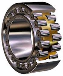
Figure 12: Double row cylindrical roller bearing
Tapered roller bearings
Tapered roller bearings are similar in design to spherical roller bearings. In tapered roller bearings the inner and outer raceways are tapered as well as the rollers. These bearings can be used for the heaviest radial and axial loads in applications prone to misalignment or shaft deflections. The high load capacity and the ability to accommodate misalignment helps obtain low maintenance costs and longer service life for bearings. Two main designs are available: single row and double row tapered roller bearings.
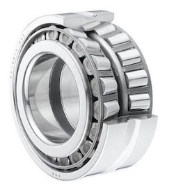
Figure 13: Tapered roller bearing
Thrust roller bearings
Similar to thrust ball bearings, there are several types of thrust roller bearings which can be single-direction and double-direction. Standard thrust roller bearings are intended for heavier axial loads than thrust ball bearings, but should not be exposed to radial loads. However, tapered thrust roller bearings and thrust spherical bearings can deal with both radial and axial forces.
- The single direction design consists of two rings, referred to as shaft and housing washers, and a single ball and cage assembly.
- The double direction design consists of an assembly of three washers and two sets of balls and cages. The shaft washer separates these assemblies.
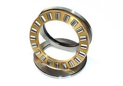
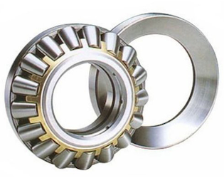
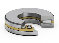
Figure 14: Thrust roller bearing (left), spherical thrust bearing(middle), and thrust tapered bearing (right)
Thrust needle bearings
Thrust needle bearings are designed for extremely high speeds, but only for axial forces. Often, adjacent machine parts serve as raceways, such as gear assemblies. This means that the bearing takes up no more room than a washer. These bearings can withstand heavy axial loads and peak loads since the rollers within one assembly have very small diameter deviations. To prevent stress peaks, a slight relief is typically provided at the roller ends to modify the contact area between the raceway and rollers.
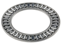
Figure 15: Thrust needle bearings
Special bearing designations
Several codes and designations exist to determine various bearing designs and design features. These codes and designations include designation for bearings with tapered bores (assigned the letter K in SKF bearings), for reinforced bearings the letter E is typically used, and many more exist. Unfortunately, not all manufacturers use the same suffixes and design features. For a good understanding of this, read our guide to bearing part numbers.
N/NJ/NU/NUP Cylindrical Bearings
One area that is typically the same worldwide, is the different designations for flange placement on bearings. These flanges are intended to deal with radial loads applied to bearings.
- NU: On the outer raceway of these bearings are two machined flanges, but there are no flanges on the inner raceway. Rolling elements and cages are assembled in the outer raceway. This bearing cannot carry thrust loads due to the lack of flanges in the inner raceway.
- N: There are two flanges on the inner raceway, no flanges on the outer raceway, and rollers and cages on the inner raceway of these bearings. The outer raceway of this bearing does not have flanges, so it cannot carry thrust loads.
- NJ: A machined flange is located on one side of the inner raceway, and two flanges are located on the outer raceway. An assembly of rollers and cages is located within the outer raceway. Because the inner raceway has an integral flange, this bearing can support axial loads and limited thrust loads.
- NUP: Bearings of this type are similar to NJ-style bearings but have a unique raceway, often referred to as the thrust collar. A thrust collar is mounted on the inner raceway's non-flange side to support an axial load in both directions. The thrust collar extends out of the bearing on one side, so the inner raceway has a slightly larger diameter than the outer raceway.
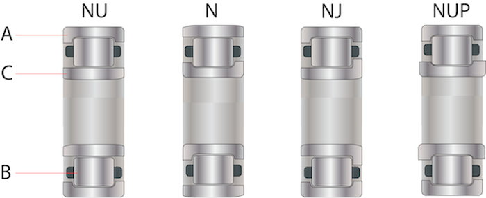
Figure 16: Examples of flange placement on bearings: the outer raceway (A), the bearing (B), and the inner raceway(C).
Rolling bearing selection criteria
Below are rolling bearing selection criteria to consider for applications:
- Available space: A bearing's bore diameter, one of the primary dimensions, is usually determined by the machine's design and its shaft diameter. Small-diameter shafts can be fitted with any type of ball bearing. In addition to deep groove ball bearings, needle roller bearings can also be used. Bearings for large-diameter shafts include cylindrical, taper, spherical, and deep groove ball bearings. In situations where radial space is limited, small cross-section bearings are preferable.
- Loads: A bearing's size is usually determined by the magnitude of the load. In general, roller bearings support heavier loads than similar-sized ball bearings, and bearings with a full complement of rolling elements can accommodate heavier loads than caged bearings. In general, ball bearings support light to moderate loads. Bearings with rollers are usually the more appropriate choice when bearings must support heavy loads or when shaft diameters are large.
- Misalignment: Misalignments are caused by shafts bending under load, when bearing seatings are not machined to the same height, or when bearings are spaced too far apart. Deep groove ball bearings as well as cylindrical roller bearings cannot accommodate any misalignment or can only accommodate minor misalignments unless by force. Bearings that self-align such as spherical roller bearings, and spherical roller thrust bearings can accommodate misalignment and compensate for initial misalignment caused by machining and mounting errors.
- Precision: Arrangements that require high running accuracy and applications that require very high speeds require bearings with a higher precision. This is typically the case in medical and aerospace applications. High precision bearings are typically made according to deep groove ball bearing or angular contact bearing standards, but have much smaller tolerances then standard bearings.
- Speed: A rolling bearing's speed is limited by the permissible operating temperature. For high-speed operation, bearings with low friction and consequently low heat generation inside them are most suitable. Thrust bearings, by their design, cannot accommodate as fast a speed as radial bearings.
- Quiet running: Depending on the application, for example, small electric motors for household appliances or office machines, the noise generated in operation can influence the bearing selection. A particular type of deep groove ball bearing with a brass cage is produced for these applications. These bearings have more space between the raceways, which enables a higher amount of lubricant to be placed inside the bearing, dampening noise levels.
- Stiffness: A rolling bearing's stiffness is determined by the magnitude of its elastic deformation under load. Since deformations are typically minimal, they can usually be neglected. The stiffness of spindle bearing arrangements or pinion bearing arrangements is critical. Roller bearings have a higher degree of stiffness than ball bearings due to the contact conditions between the rolling elements and raceways. However, this deformation does play a role in lubrication. Under a hydro-elastic lubrication regime this deformation is a favorable effect, learn more in our tribology guide.
- Mounting and dismounting: When bearings with cylindrical bores have separable designs, they can be mounted and dismounted more efficiently, especially if interference fits are required on both rings. If frequent mounting and dismounting is required, separable bearings are preferable since each bearing ring can be fitted independently of the other. Tapered bore bearings can easily be mounted on a cylindrical shaft seating or a tapered journal using an adapter or withdrawal sleeve. Learn more about bearing installation in our bearing puller article.


