AW1 Actuators for Electric Ball Valves - With & Without Relays
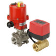
Figure 1: Electric ball valve with an integrated relay
AW1 actuators for electric ball valves can come with or without integrated relays. These actuators are compatible with ball valves from the BW2 (2-way) and BW3 (3-way) series.They automate the precise control of flow in fluid control system applications, with integrated relays providing additional control and automation capabilities. This article explores the wiring configurations for AW1 actuators, focusing on the differences between two-point and three-point control signals.
Electric ball valve wiring
The "control signal" in an electric ball valve refers to the electrical signal used to command the actuator to either open or close the valve. There are two types of control signals:
- Two-point control: Uses three wires total (two power wires and one control wire) with a single control wire for on/off operation. Ideal for applications requiring simple on/off functionality, such as basic heating systems and home appliances.
- Three-point control: Uses three wires total (one common wire and two control wires) with separate control wires for opening and closing. Suitable for applications requiring more precise control with intermediate positions, such as building automation, industrial processes, and advanced HVAC systems.
Two-point control for electric ball valves
AW1 actuators with integrated relays have an "R" in their reference name, for example, AW1-R230AC.
Working
Two-point control for electric ball valves typically involves the use of integrated relays (electrically operated switches) within the actuators.
- Relay: The relay is embedded within the actuator. It acts as an intermediary between the control signal and the actuator's motor.
- Control circuit: The control circuit sends a low-power signal to the relay.
- Actuator motor: When the relay receives the control signal, it activates the motor within the actuator.
- Valve operation: The motor then opens or closes the ball valve based on the received signal.
This setup ensures that the control system only needs to handle low-power signals, while the relay and actuator manage the higher power required to operate the valve.
How to wire an actuator with relay
The actuator has three wires - phase, neutral and control wire (Figures 2 and 3). These wires are used to connect the actuator to the power supply and control system.
Figure 2 shows the wiring diagram of AW1-R230AC and AW1-R024AC (On/Off control)
- Power supply connections: Blue and brown wires must be connected to the power supply at all times.
- Control wire: 'C' is the control wire. This wire is used to send the signal to open or close the valve. Sending power to the control wire opens the valve and disconnecting the power will close the valve.

Figure 2: AW1-R230AC and AW1-R024AC (On/Off control) wiring diagram: Blue and brown must be connected to power supply at all times. Neutral (A), Close (B), and Open (C)
Figure 3 shows the wiring diagram of AW1-R024DC and AW1-R012DC (On/Off control)
- Power supply connections: Black and brown wires must be connected to the power supply at all times.
- Control wire: 'C' is the control wire.
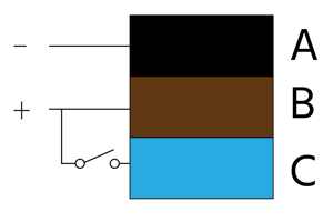
Figure 3: AW1-R024DC and AW1-R012DC (On/Off control) wiring diagram: Black and brown must be connected to power supply at all times. Neutral (A), Close (B), and Open (C)
The integrated relay provides simplified control by handling the direction of rotation internally. The control system only needs to provide an on-off signal to the single control wire. It enhances reliability, reduces wiring complexity, and enables seamless integration with control systems such as PLCs (programmable logic controllers) or building management systems.
Also, the actuator has built-in limit switches. These switches stop the motor once the valve is fully open or fully closed. This means the actuator only uses energy while it is moving the valve, not when it is holding it in the open or closed position.
Three-point control for electric ball valves
Note: AW1 actuators without an "R" in their reference name, such as AW1-230AC, do not have an integrated relay. This means that the control system must handle the direction of rotation and power management directly.
Electric ball valves designed for three-point control typically don't have built-in relays. The actuator has a three-wire connection (Figures 4 and 5) designed for three-point control. This type of control allows the actuator to rotate the ball valve in both directions using two control wires, while one wire is permanently connected to the ground (Figure 4 labeled B and C). The actuator is supplied with a cable and includes limit switches to ensure energy is only consumed during the opening or closing of the valve.
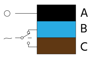
Figure 4: AW1-230AC and AW1-024AC (three-point control) wiring diagram: The black wire is permanently connected to the neutral. Connecting the blue wire to the positive rotates the ball valve in one direction, while connecting the brown wire to the positive rotates the valve in the opposite direction.

Figure 5: AW1-024DC and AW1-012DC (three-point control) wiring diagram: The blue wire is permanently connected to the negative terminal. Connecting the black wire to the positive rotates the ball valve in one direction, while connecting the brown wire to the positive rotates the valve in the opposite direction.
Note: Always observe the color coding of the wires and the manufacturer's wiring diagram given in the valve manual. Also, never connect the two control wires at the same time as this could damage the actuator.
Integrated relays and change in control
If the actuator comes with an integrated relay, the control scheme changes from three-point control to two-point (on-off control). This means the actuator no longer requires two separate control wires to manage the direction of rotation. The relay internally manages the direction, making the overall control scheme easier to implement and reducing the complexity of the external control logic. When a control signal is received, the relay activates the appropriate contacts to either open or close the valve, thus controlling the direction of rotation without requiring separate external control wires for each direction.
Read our electric ball valve installation article for more information on the installation process and post-installation checks for an electric ball valve.