


Solenoid Valve Installation
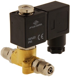
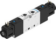
Figure 1: Solenoid valve
Solenoid valves, which are electrically controlled, are frequently utilized in industrial control systems to manage the flow, direction, speed, and other characteristics of a medium. Proper installation is crucial to achieving optimal performance from a solenoid valve. This article provides guidance on the effective installation and maintenance of solenoid valves.
Table of contents
- Checking the valve properties
- Pipe system checks
- Positioning the solenoid valve on the pipe system
- Mounting the coil to the solenoid valve
- Installing the connector
- Commissioning
- Causes of improper valve operation
- FAQs
View our online selection of solenoid valves!
Checking the valve properties
Before starting the installation, it is essential to verify that the solenoid valve is suitable and safe for the desired application. For this, carefully read the user manual and safety instructions associated with the brand and type of the valve. Check the valve properties on the type label and verify if the specifications match the application's requirements. Figure 2 shows an example of type labels on the coil (Figure 2 left) and valve (Figure 2 right).
- Coil
- A: Coil code
- B: Voltage and frequency
- C: CE- mark
- D: Ingress protection grade. This standard defines the sealing effectiveness levels against intrusion from foreign bodies like dirt, tools, and liquids.
- Valve
- E: Valve code
- F: Position (Normally open or normally closed)
- G:Pipe thread
- H:Seal material
- I: Orifice diameter
- J: Operating pressure (min-max) for AC/DC current
Always check to ensure that the operating voltage and frequency of the coil match the supply given; otherwise, the coil may burn out.
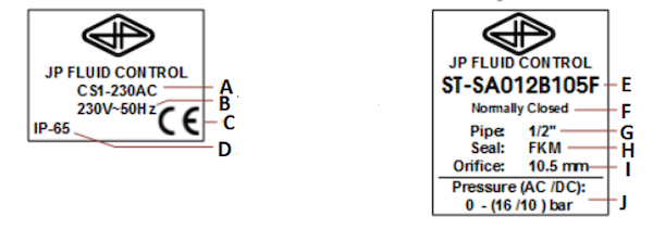
Figure 2: Coil (left) and valve (right) nameplates on a JP Fluid Control solenoid valve
Pipe system checks
A solenoid valve is usually used to direct, start, or stop the fluid flow from a fluid supply pipe to a piece of equipment. Therefore, one port of the solenoid valve is connected to the main supply line that carries the fluid, and the other port can be connected to the device or outlet pipe headed to the device. The electrical signal on the lead wires determines when to turn the valve on and off.
- Ensure that the circuit is not under pressure and the system is cooled down before proceeding.
- Check the pipes for dirt (rust particles, cuttings, leaves, etc.). It is recommended to flush the pipes before installing the valve. Small particles of dirt in the pipe can enter the valve and lead to blockage or leakage. This is one of the main reasons why solenoid valves malfunction. This problem can be solved by opening and cleaning the valve, but preventing dirt from entering the valve is a better choice. Install a pipe filter on the inlet side of the solenoid valve for added safety.
- The pipes on both sides of the valve (inlet and outlet) must be fastened securely, and the same connection types must be ensured on both sides.
- There is a pilot exhaust from the top of the solenoid for pneumatic solenoid valves when de-energized. Connect the pilot exhaust to the main exhaust pipe if the inert gas or air cannot be expelled directly into the atmosphere.
Positioning the solenoid valve on the pipe system
The solenoid valve consists of two main components: a solenoid and the valve body. The valve body contains the input and output ports, and the solenoid is connected to the valve body once it is installed in the pipe.
- To allow for cooling, sufficient space must be maintained around the valve. It is recommended to install the valve in a dry and ventilated environment as during usage, the valve does get hot.
- Most solenoid valves can be used in one flow direction only. Be aware of the flow direction of the medium when installing the valve. An arrow on the valve body often indicates the correct flow direction.
- The pipes on both sides of the valve must be securely fastened. Use a wrench for both the valve and the pipe while tightening. Prevent unnecessary stresses in the system.
Coil mounting direction
- The best way to install the valve is with the coil facing upward, typically at 90 degrees of the valve body (see Figure 3). This ensures that the armature tube points upwards, thus reducing the risk of any sediments in the media falling into the tube and restricting the armature movement.
- Always use counterbalance while tightening up connections to the pipe (use a spanner on both the connected pipe and the valve body).
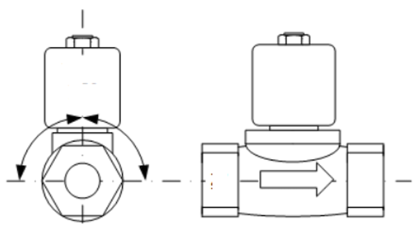
Figure 3: Positioning the solenoid valve (left) and the direction of media flow (right)
Mounting the coil to the solenoid valve
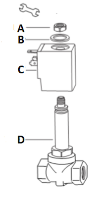
Figure 4: Mounting the solenoid coil
The solenoid is an electric coil with a movable ferromagnetic core (plunger) in its center. In the rest position, the plunger closes off a small orifice. An electric current through the coil creates a magnetic field. The magnetic field exerts an upwards force on the plunger, opening the orifice. This is the basic principle used to open and close solenoid valves. Read our article on solenoid valves for more details on constructing a solenoid valve.
Mount the coil on the solenoid valve. Never connect the coil to the power supply when it is not mounted on the solenoid valve; else, the coil may burn out. Follow the user manual to ensure the correct assembly of the parts. Tighten the nut sufficiently to ensure that the coil does not rotate or vibrate, but avoid over-tightening to prevent damage. A guideline for the tightening torque is 5 Nm, and the process is shown in Figure 4.
- A: Nut
- B: Washer
- C: Coil
- D: Valve
Installing the connector
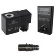
The connector is used for connecting the solenoid valve to the power supply. For example, the Burket 2518 cable plug is designed according to DIN EN 175301-803 Form A. These connectors are designed to meet various overvoltage protection requirements and function within certain voltage limits. Form A refers to the distance between the pins, as seen in Figure 6. The majority of solenoid valves are compatible with this standard. Before ordering a connector, check if the valve connection has the same form size.
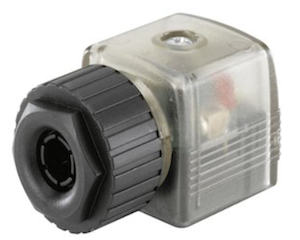
Figure 5: Burkert 2518 Connector with LED
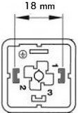
Figure 6: DIN EN 175301-803 Form A standard sizing
- Note the colors on the cable leads. Mostly yellow or green shaded cable is the earth (Labeled 3 in Figure 7A), and the other leads can be connected to the phase and neutral supply (Labeled 1 and 2 in Figure 7A). Check the valve manual for the exact color coding for the cables.
- Use a round cable. Connect terminals (1) and (2) to the power supply. The polarity does not matter (Figure 7 labeled A) for a DC coil. However, it is important to consider the polarity of these wires when connecting to external components like a timer or an LED connector.
- Always connect the ground. Never use the piping as earthing.
- Connect the connector to the coil (Figure 7 labeled B). Make sure that no moisture can come between the coil and the connector. Use a torque of 0.5Nm for the mounting screw.
- Position the cable in a way that condensation drops can not slide along the cable into the connector (Figure 7 labeled C).
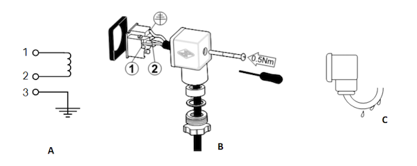
Figure 7: Connecting wires (A), attaching the connected to the coil (B), condensation drops on the cable (C) of a solenoid valve
Commissioning
Turn the power supply on only when the valve is correctly installed and can be started safely. In case the solenoid valve does not function properly after installation, check for the following causes:
- Blocked valve: The valve may be blocked because of dirt. Small dirt particles can block the small channels and openings in the valve. Although the pipes seem clean during installation, they may contain dirt like rust particles, sand, cutting chips, etc. If this happens, open the valve carefully and clean the parts. Always follow the instructions in the user manual. Ensure that the valve is properly reassembled.
- Wrong flow direction: The valve may be connected in the wrong flow direction. Check the flow direction indicated on the valve body with an arrow or reverse the valve if necessary.
- Low differential pressure:Indirect acting solenoid valves (also called servo-operated or pilot operated) use the pressure differential of the medium over the valve inlet and outlet ports to open and close the valve. If the pressure across the indirectly operated valve is too low (less than 0.5 bar), the valve will not open properly. In this case, a (semi) direct operated valve should be used.
-
Water hammer: A water hammer is a typical consequence of a high flow rate and pressure in pipes with small diameters. A few solutions for water hammer are listed below:
- Increase the pipe diameter to reduce the fluid velocity.
- Reduce the pressure with a pressure-reducing valve before the solenoid valve.
- Dampen the water hammer by using a flexible hose or buffer before the solenoid valve.
- Use a solenoid valve with a longer response time. This reduces the pressure transients.
Read our article on solenoid valve troubleshooting for more details on the possible causes and fixes when a solenoid valve malfunctions.
Causes of improper valve operation
- Low voltage: Check the voltage across the coil terminals using a multimeter. The recorded voltage must be at least 85% of that printed on the nameplate.
- Incorrect pressure: Check the valve pressure using a pressure gauge or pressure meter. The pressure to the valve must be within the range specified on the nameplate.
- Faulty control circuits: Energize the solenoid and check the electrical system. A metallic click sound signifies that the solenoid is working. The absence of the click sound indicates a problem with the power supply. In this case, check for a blown or loose fuse, a grounded or open-circuited coil, or broken lead wires.
- Burned-out coil: Check for an open-circuited solenoid coil. Replace the coil if necessary.
Perform the following steps to replace a solenoid coil:
- Disconnect the supply wires and grounding from the coil.
- Remove the training clip and slip the coil out of the core tube assembly.
- Install the new coil and replace the retaining clip.
- Make necessary electrical connections to the coil.
Note: When replacing a coil, use a screwdriver to lever it from the armature. Read our article on replacing a solenoid valve coil for more information.
FAQs
Can a solenoid valve be installed vertically?
Ideally, the solenoid valve must be mounted in a horizontal pipe run with the solenoid vertically on top. This ensures that the armature tube points upwards, thus reducing the risk of any sediments in the media falling into the tube and restricting the armature movement.
Where are solenoid valves installed?
Install the solenoid valve with the inlet port connected to the flow upstream and the outlet port connected downstream. Also, check for the arrow on the valve’s body that indicates the direction in which the media should flow.


