


Solenoid Valve Symbols

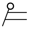
Figure 1: Piping and instrumentation diagram (P&ID)
Solenoid valve symbols are used to represent the valve’s function and role in a system without showing its physical shape. In fluid machinery and process design, it would be difficult to draw detailed pictures of every valve and component. Instead, standardized symbols are used in fluid power diagrams and piping and instrumentation diagrams (P&ID) to show how components connect and interact. This article explains the symbols used for solenoid valves, their circuit functions, and practical application examples.
Table of contents
- Solenoid valve functions
- Solenoid valve symbols
- Solenoid valve symbols in a piping and instrumentation diagram (P&ID)
View our online selection of solenoid valves!
Solenoid valve circuit functions
Valves are designated with two numbers, for example, in a 2/2-way valve, the first number indicates the number of connection ports. The second number is the number of switching states. A 2/2 way valve has two pipe connections (inlet and outlet) and two switching states (open and closed). Normally closed (NC) or normally open (NO) determines if the valve is closed or open in a de-energized state. A 3/2 way valve has three ports and two switching states. In each switching state, a different port is closed off. More ports and switching states are possible.
Solenoid valve symbols
1. Solenoid valve symbols in fluid power diagrams
Fluid power drawings are crafted up by engineers to understand and analyze power units. These diagrams have standard-based graphic symbols representing the complete operation and direction of fluid flow within a power unit.
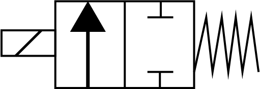
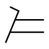
Figure 2: A 2/2 valve symbol
Figure 2 shows the symbol of a 2/2 valve used in fluid power diagrams. For each state of the valve, a single square is drawn. The symbol has the same number of squares as the valve has positions. For example, A 2/2 valve has two states (open and close) and is therefore represented by two adjacent squares, as shown in Figure 2, and a 5/3 valve is represented by three adjacent squares.
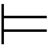
The right-hand square shows the valve in its rest (non-actuated position), and the left-hand square corresponds to a valve in its work (actuated) position in a 2/2 valve. For a 5/3-way valve, it has three squares. The right-hand square shows the port states in the rest position and the other two squares indicate how the fluid flows between ports when the valve is actuated to that state. The method of valve actuation is indicated by symbols added to the squares. The pilot control is shown attached to the left-hand square and the return control on the right-hand square. Each square shows how the medium flows between the ports. The arrows indicate the connection between ports and the preferred flow direction. Bidirectional ports are represented by double-sided arrows indicating to and fro fluid flow between the ports (discussed later in the article). Closed ports are indicated by a 'T'. Table 1 shows the standard symbols used for actuating a valve.
Table 1: Control mechanism for a valve
| Actuation | Symbol | Mode of operation |
Manual |
 |
Manual operation |
 |
Push button | |
 |
Lever | |
 |
Foot operation | |
 |
Detent | |
 |
Spring | |
Mechanical |
 |
Pin |
 |
Roller control | |
| Pneumatical | 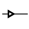 |
Air operated |
| Electrical | 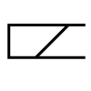 |
Coil |
Examples
Normally open 2/2 way solenoid valve symbol
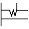
The majority of solenoid valves are normally closed 2/2-way valves. The two adjacent squares represent the two states of the valve. An arrow in the right-hand square indicates that the valve is normally open, and the arrow points in the direction of fluid flow while at rest. The ‘T’ symbol on the left-hand side square shows that the valve closes upon actuation. The symbol of solenoid coil on the left-hand side and spring on the right-hand side indicates the means of pilot control and return control for the valve operation respectively.
Note: The actuator symbols (spring and coil) are often left away, creating ambiguity about the electrically energized state (as shown on the right-hand side of Figure 3). Also, the left and right squares are swapped by some manufacturers leading to confusion, especially when the actuator symbols are left out.
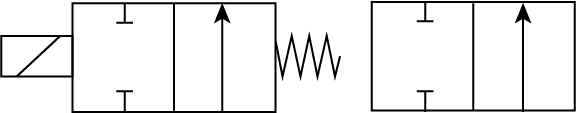
Figure 3: Normally open 2/2 way solenoid valve symbol
Normally closed 2/2 way solenoid valve symbol
Figure 2 shows a 2/2 valve symbol in the normally closed state. The two adjacent squares represent the two states of the valve. The ‘T’ symbol in the right-hand square indicates that the valve is normally closed, and the arrow in the left-hand square points in the direction of fluid flow while the valve is actuated. The symbol of solenoid coil on the left-hand side and spring on the right-hand side indicates the means of pilot control and return control for the valve operation respectively.
3/2 way solenoid valve symbols
3/2-way solenoid valves have two positions and three connection ports, hence a single valve can be used to control the fluid flow in two circuits. These valves can be used for multiple applications, such as switching between two circuits or actuating a hydraulic cylinder. The symbols in Figure 4 show different circuit functions of 3/2 way valves. In each symbol, 1, 2, and 3 represent three ports of the valve. The symbol of solenoid coil on the left-hand side and spring on the right-hand side indicates the means of pilot control and return control for the valve operation respectively. The various configurations are explained below:
- A: When the valve is at rest position, the fluid flows from port 2 to 3 while port 1 is completely closed (indicated by a ‘T’ symbol at port 1 in the right-hand square). When the valve is actuated, the fluid flows from port 1 to 2 while port 3 remains closed (indicated by a ‘T’ symbol at port 3 in the left-hand square).
- B: When the valve is at rest position, the fluid flows from port 1 to 2 while port 3 is completely closed (indicated by a ‘T’ symbol at port 3 in the right-hand square). When the valve is actuated, the fluid flows from port 2 to 3 while port 1 remains closed (indicated by a ‘T’ symbol at port 1 in the left-hand square).
- C: When the valve is at rest position, the fluid flows from port 1 to 3 while port 2 is completely closed (indicated by a ‘T’ symbol at port 2 in the right-hand square). When the valve is actuated, the fluid flows from port 1 to 2 while port 3 remains closed (indicated by a ‘T’ symbol at port 3 in the left-hand square).
- D: When the valve is at rest position, fluid can flow to and fro between ports 1 and 3 with port 2 being shut completely(indicated by a ‘T’ symbol at port 2 in the right-hand square). When the valve is actuated fluid can flow to and fro between ports 1 and 2 with port 3 being shut completely(indicated by a ‘T’ symbol at port 3 in the left-hand square).
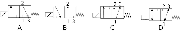
Figure 4: 3/2 way solenoid valve symbols
2. Solenoid valve symbols in a piping and instrumentation diagram (P&ID)
Piping & instrumentation diagram (P&ID)
A piping and instrumentation diagram (P&ID) is a detailed graphical representation of a process that includes both the hardware and software (like equipment, piping, and instrumentation) necessary to design, assemble, and operate the system. Most manufacturing systems have steam, compressed air, water, and other processes that require piping for transmission from one point to another. Several instruments control these forms of energy, processes, and media which are usually in the form of gauges, valves, and pumps.
A P&ID in a control system is similar to the circuit diagram of an electronic circuit. The diagram has all of the components designed for a particular process and it is used by engineers, operators, and maintenance personnel working in the unit to read and perform their job. There can be several processes on a single P&ID, and in this case, it is advisable to segment the whole P&ID into individual processes for better understanding.
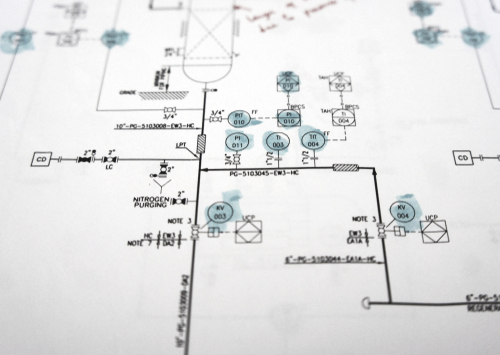
Figure 5: Piping and instrumentation diagram (P&ID)
Solenoid valve symbols in a P&ID
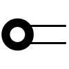
Typical solenoid valve symbols used in a P&ID diagram are shown in Figure 6. These symbols are not as descriptive as those used in fluid power diagrams. Arrows are used to show the direction of fluid flow in 3-way and 4-way valves. The arrows indicate de-energized flow paths that give fluid flow direction when the valve is at rest (non-actuated). The various labels are:
- A: Two-way on-off solenoid valve
- B: Angle on-off solenoid valve
- C: Three-way on-off solenoid valve
- D: Four-way plug or ball on-off solenoid valve
- E: Four-way five-ported on-off solenoid valve
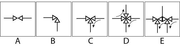
Figure 6: Solenoid valve symbols: A: Two-way on-off solenoid valve, B: angle on-off solenoid valve, C: three-way on-off solenoid valve, D: four-way plug or ball on-off solenoid valve, and E: four-way five-ported on-off solenoid valve.
The symbols of actuators for solenoid valves are given in Figure 7. The various labels are:
-
A: Automatic reset on-off solenoid actuator
- Automatic reset on-off solenoid actuator ensures that the valve changes state without the influence of an external operator, and this method of actuation is ideal for process automation.
-
B: Manual or remote-reset on-off solenoid actuator
- Manual reset solenoid valves are used in applications demanding extreme safety checks before stopping/starting the process. Hence, the valve cannot be operated electrically and the valve switches on when the solenoid receives electrical supply by manual operation.
-
C: Manual and remote-reset on-off solenoid actuator
- Manual and remote-reset on-off solenoid actuator ensure both automatic as well as manual actuation of the solenoid valve.
-
D: Modulating solenoid actuator
- A modulating solenoid actuator accurately positions the valve anywhere between the fully open and fully closed position (i.e. between 0° to 90°). This is necessary for applications that require a variation in flow rate.
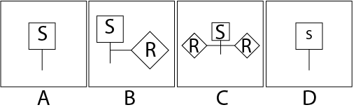
Figure 7: Solenoid valve actuator symbols
A P&ID diagram usually includes the symbol of actuated valves, as shown in Figure 8. Note that the P&ID symbols represented in Figures 6-8 are for informational purposes only, and these can change from one company to the other. Always refer to the P&ID legend of the concerned company for the symbol chart.
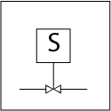
Figure 8: Automatic reset on-off 2-way solenoid valve symbol
Standardization of symbols
The International Society Of Automation (ISA) has stipulated a strict set of standards for P&ID symbols, but still, there are different ways of representing valves. There are transparent discrepancies between valve types across various companies and libraries within a simulation tool. But this is not a protruding issue because all components are also described by text, a unique model called the part number, a tag number which is a specific component in the system, and are described in detail in a legend that goes along with the drawing. Be consistent with the symbols throughout the drawing so that the P&ID diagram can be easily comprehended by everyone who works with it.
Example
A remotely placed process control valve can be actuated and controlled by an intermediate control valve, as shown in Figure 9. The air supply line (Figure 9 labeled C) is controlled by a 3-way solenoid valve (Figure 9 labeled A). It either vents the air (Figure 9 labeled D) or sends it to the process control valve (Figure 9 labeled B). The intermediate control valve is positioned to supply energy to the process control valve.
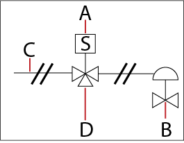
Figure 9: Application of a solenoid valve to guide a process control valve


