


How To Select And Size Safety Valves & Pressure Relief Valves


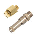
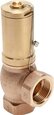
Figure 1: Pressure safety valve (left) and pressure relief valve (right)
Safety valves and pressure relief valves ensure the safe operation of pressurized systems. Both types of valves work as overpressure valves, protecting piping systems, equipment, and vessels from excessive pressure. As overpressure can lead to damage and even explosions, it is important to correctly size and select these valves. This article discusses five criteria to consider when sizing and selecting pressure relief valves and safety valves:
- Set pressure
- Back pressure
- Blow-off capacity
- Temperature
- Valve and seal material
Table of contents
View our online selection of safety and relief valves!
Set pressure
A pressure relief or safety valve’s set pressure, or response pressure, is the pressure at which the valve opens. The set pressure must not exceed the system’s maximum allowable working pressure (MAWP). The system’s MAWP must be at least 10% higher than the highest expected operating pressure assuming normal circumstances.
Figure 2 illustrates the pressure profile differences between pressure relief valves and pressure safety valves. Learn more by reading our article on pressure safety valve vs relief valve for a detailed comparison between both valve types.
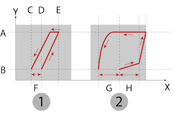
Figure 2: Discharge flow for relief valves (1) and safety valves (2). These valves alternate between fully open (A) and fully closed (B). Other important characteristics are the reseating pressure (C), set pressure (D), maximum relieving pressure (E), blowdown (F and G), and simmering value (H).
Back pressure
Back pressure is the pressure on the outlet side of the safety or relief valve. It can be constant or variable and can affect the downstream pressure of the valve and cause chatter (rapid opening and closing). This is because increased back pressure can lower the set pressure and cause the valve to pop open repeatedly. Chatter can damage the valve. If the system has variable back pressure, ensure that the back pressure doesn’t exceed 10% of the valve’s set pressure.
Blow-off capacity
Pressure relief and safety valves must relieve pressure at a certain blow-off capacity. Several factors determine a safety valve’s blowoff capacity or relieving capacity, such as the valve’s geometry, media temperature, and relief discharge area. Blow-off capacity is expressed in cubic meters per hour (m³/h), gallons per minute (gpm), or pounds per hour (lbs/hr).
A pressure relief valve must relieve an adequate fluid amount to ensure that the system pressure never exceeds the specified overpressure. Therefore, it is crucial to evaluate all possible causes and sources that lead to an overpressure in the system. Some examples of these causes could be a failure of a stop valve to close, failure of a control system or pump, fire, uncontrolled chemical reactions, and vessel isolation. An analysis of these factors determines the required relieving capacity of the safety/pressure relief valve. The gross rated relieving capacity of the safety valve (or valves) must be larger than the required capacity determined from the worst-case system failure analysis tests.
Temperature
The media temperature affects the viscosity (the media viscosity decreases with rising temperature) and, thus, the flow of the media. This, in turn, affects the necessary blow-off capacity. Furthermore, the temperature must be considered when selecting the valve and seal material.
Valve and seal material
The material must be compatible with the system’s media and operating temperature. For example, stainless steel pressure relief valves are suitable for corrosive media and high operating temperatures. Brass pressure relief valves and safety valves are more suitable for neutral and non-corrosive media. Read our article on the chemical resistance of materials for more details on the suitability of various materials for different media.
Soft seat vs hard seat safety valve
A hard seat safety valve is a metal-to-metal seated valve. These valves have a metal disc or ball as the internal sealing surface against the orifice. A hard seat safety valve is an excellent choice for high-temperature applications and corrosive environments. A soft seat safety valve uses an elastomer material like Teflon, FKM, PTFE, or Nitrile. Soft seat safety valves are not suitable for applications involving extremely high temperatures, but they provide a higher degree of seal tightness compared to hard seat safety valves.
FAQs
How is pressure safety or relief valve size determined?
Consider the set pressure, back pressure, blowoff capacity, temperature, and valve material while selecting and sizing pressure relief or safety valves. The maximum allowable working pressure (MAWP) of the system should be at least 10% higher than the highest expected operating pressure assuming normal circumstances.
Can a relief valve be oversized?
Oversizing a relief valve is a common practice. However, oversizing can lead to high inlet pressure or backpressure. Choking can occur inside the valve, which can damage it.

