


Pneumatic Gripper - How They Work
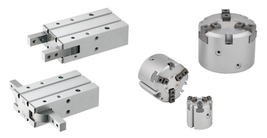
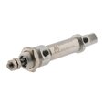
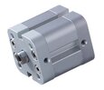
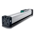
Figure 1: Pneumatic grippers
A pneumatic gripper is a pick-and-place device that uses compressed air to operate gripper jaws, also called fingers. These fingers, similar to human fingers, help in grasping, holding and releasing the work pieces. Commonly, they have 2 fingers (parallel or angular) or 3 fingers with a single or double acting cylinder for control. They are mostly used in automated manufacturing processes to grip a work piece. The work pieces can range from small objects like circuit boards or chips to large objects like an engine block. Figure 1 shows examples of pneumatic 2 finger and 3 finger grippers.
Table of contents
- Advantages of pneumatic grippers
- Pneumatic gripper working principle
- Pneumatic 2 finger and 3 finger grippers
- Gripping force
- Selection criteria
- Applications
View our online selection of pneumatic grippers and cylinders!
Advantages of pneumatic grippers
The advantages of pneumatic grippers include:
- Light weight
- Cost effective
- High gripping force
- Ability to grip variety of workpiece configuration
- Adjustable gripping force
Pneumatic gripper working principle
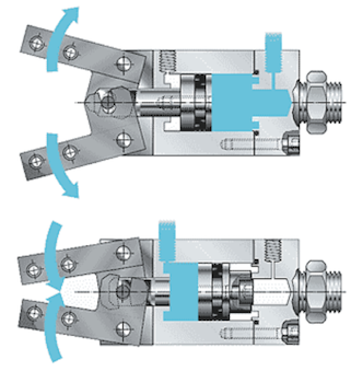
Figure 2: Operating principle of pneumatic 2 finger angular gripper
The gripper is connected to the compressed air supply system. As the compressed air is introduced into the cylinder, it powers the piston rod. The piston rod is connected to the gripping fingers. As the air pressure moves the piston up and down, the fingers open or close in a parallel or angular manner. This mechanism can be used in pick-and-place operation or to change the orientation of the object.
Figure 2 shows the operating principle for a pneumatic 2 finger angular gripper. This is a double cylinder design. Therefore, when compressed air is connected to the back cylinder (Figure 2 Top) it pushes the piston forward, which opens the pneumatic gripper’s fingers. When compressed air is connected to the front cylinder (Figure 2 Bottom) it pushes the piston backward, which closes the pneumatic gripper’s fingers.
The pneumatic grippers can be categorized based on motion of gripping fingers, gripping mechanism and configurations. Common ones are discussed below:
Parallel gripper
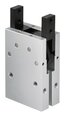
As the name suggests, the parallel gripper moves its fingers parallelly with respect to the gripper body. The parallel gripper type is the most commonely used as custom grippers are easy to design and installation is straight forward due to only one axis of motion. They can also handle workpieces of a wide variety of shape and sizes and can accommodate dimensional variations. Figure 3 shows finger movement.
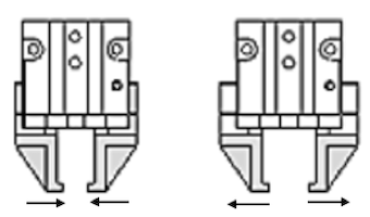
Figure 3: Pneumatic parallel grippers closing (left) and opening (right)
Angular gripper
The pneumatic angular gripper can move its fingers in a radial manner, opening and closing around a central pivot point. They are often used in applications where limited space is available as the jaws can move up and out of the way. These grippers are good for holding large workpieces with odd shapes. Figure 2 shows finger movement.
Pneumatic 2 finger and 3 finger grippers
Pneumatic 2 finger grippers are the most commonly used grippers. It provides 2 mounting locations for the fingers. The fingers move in a synchronous manner, opening and closing towards the central axis of the gripper.
3 finger grippers are great to handle round objects and provide more gripping force than 2 finger grippers. It provides 3 mounting locations for the fingers. The fingers open and close towards the central axis of the gripper body. The 3 fingers provide more support and accurate centering in comparison to 2 finger grippers.
External and internal gripping
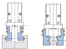
Figure 4: Types of pneumatic grippers based on gripping mechanism: internal gripping (left) and external gripping (right)
Based on the type of grip, pneumatic grippers can be categorized as internal, external, or combined. Examples are discussed below and shown in Figure 4.
- Internal gripping: Internal grippers use opening force to hold the part and grips the object through its internal surface.
- External gripping: External grippers use the closing force to hold the work piece and grip the object from the outer surface. It is the most common gripping mechanism.
- Combined gripping: Uses a combination of external and internal gripping.
Single acting and double acting grippers
The pneumatic grippers can have a single or double acting configuration. The single acting pneumatic grippers contain a spring to assist drive in one direction (either open or close).
Pneumatic grippers are mostly designed to be double acting. They can be actuated by compressed air to both open and close. This feature allows internal and external clamping. The double acting grippers can have spring assist feature to hold the workpiece in case the air pressure is lost.
Magnetic gripper
Magnetic grippers are suitable for handling ferromagnetic objects. The grippers are fitted with permanent magnets at their core. Depending upon the strength of the magnet, it can be used to handle a variety of object sizes. However, it is important to note that the permanent magnets tend to lose their magnetic property at higher temperature (above 150°C).
Finger shape
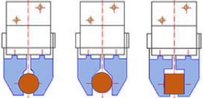
Figure 5: Shape of fingers for pneumatic grippers: encompassing (left), friction (middle), retention (right)
Generally, the pneumatic gripper’s fingers use friction for gripping force. But these fingers can also be designed alternatively to reduce size and gripping force required for the application. The encompassing and retention shape increase the stability and decrease the force required for the grip. Figure 5 shows some common examples of different finger shapes.
Repeatability
Repeatability is the measure for maximum position accuracy that the gripper can achieve. The pneumatic grippers can have different repeatability based on the number of fingers and speed of operation. So, the repeatability must be determined based on the precision required for the application.
Gripping force
Gripping force is the force exerted by the gripper fingers on the workpiece. This force can differ depending upon the air pressure, coefficient of friction and gripping conditions between fingers and the work piece. The gripping force for just frictional holding when the work piece does not drop when gripped is calculated as:

Where:
- F = Gripping force of a single finger (N)
- m = Mass of the workpiece (kg)
- g = Gravitational acceleration (9.81 m/s²)
- a = Acceleration from dynamic movement (m/s2)
- n = Number of fingers (n=2 for two-finger gripper; n=3 for three finger gripper)
- μ = Coefficient of friction
- S = Safety factor
If your finger design and method of gripping the object is different than just frictional holding, a different gripping force formula may be required.
Coefficient of friction
Below is a table of the coefficient of friction of common materials. However, these numbers are an initial benchmark as they will be different for every application and should be verified.
| Workpiece material | Jaw material | Friction coefficient μ |
| Steel | Steel | 0.25 |
| Steel | Aluminum | 0.35 |
| Steel | Plastic | 0.50 |
| Aluminum | Aluminum | 0.49 |
| Aluminum | Plastic | 0.70 |
| Plastic | Plastic | 1 |
Safety factor
This is simply a recommendation and the safety factor for your particular application may be different:
- 2 - for normal use
- 3 - for movement in several directions
- 4 - for shocks, fast accelerations or decelerations
Mounting options
The mounting holes are on the bottom, side and front of the gripper and provide secure mounting options. In Figure 6 below, A, C, and D represent the mounting holes. Depending upon the application, either side can be selected for mounting. The air ports are represented by B.
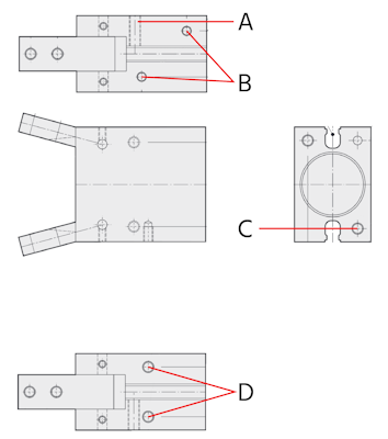
Figure 6: Mounting options for 2 finger angular gripper: mounting holes (A, C, D) and air port (B).
Sensors
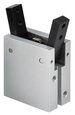
Sensors can be installed alongside pneumatic grippers to monitor and control the operating position of the fingers. Sensor switches or proximity sensors can be installed on the pneumatic grippers. They can be inserted into the grooves present in the body as seen in Figure 7. These sensors can detect the open or closed position of the fingers. Proximity sensors can detect the proximity by sensing the object and provide the information back to the controller.
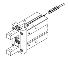
Figure 7: Installing sensor switch
Selection criteria
- Gripping force: The effective gripping force can be calculated using the formula in this article.
- Workpiece weight: The gripping force must be able to support the weight of the workpiece during the operation.
- Air pressure: Air pressure should be considered as it has direct effect upon the gripping force and influences the gripper sizing.
- Configuration of work piece: The shape of the work piece will help to determine whether 2 or 3 finger grippers can be used. 2 finger grippers are commonly used and can be used for wide variety of objects. 3 finger grippers are suitable for round or cylindrical objects.
- Type of gripper: The gripper may have external or internal grip depending upon the workpiece.
- Environment: Pneumatic grippers should be selected based on the operating environment. Grippers designed for clean environments may fail in harsh environments.
Applications
The pneumatic grippers are commonly used in following industries:
- Robotics
- Medical device manufacturing
- Pharmaceutical and biotech industry
- Plastic molding and injection
- Laboratory processing
- Automation