


Pneumatic & Electric Ball Valve - How They Work
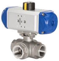
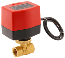
Figure 1: Pneumatic (left) and electric (right) ball valves
Ball valves can be automated with either a pneumatic actuator (pneumatic ball valves) or an electric actuator (electric ball valves) for remote control and automation. The choice between a pneumatic or an electric actuator depends on the specific application. This article explores the working, and features of pneumatic and electric ball valves in detail. Also, there is a comparison table towards the end to choose the right device for your application.
Table of contents
- Ball valve overview
- Actuator overview
- Pneumatic actuators
- Electric actuators
- Combining an actuator and a ball valve
- Comparison between pneumatic and electric ball valves
- Application examples for pneumatic or an electric ball valve
View our online selection of electric and pneumatic ball valves!
Ball valve overview
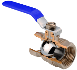
Figure 2: A manual ball valve sectional view showing the ball valve components
A ball valve is a quarter-turn valve that controls the flow of a media by having a hollow rotating ball, as seen in Figure 2. The figure shows the main components of a manual ball valve in a sectional view. When the hollow portion of the ball is in line with the flow (pipe or hose), the valve is open and the media can flow through. The valve closes when the solid portion of the ball is in line with the flow, which is done with a 90-degree rotation (hence the name quarter-turn valve) of the ball.
It is also possible to position the valve between fully open and fully closed, which allows you to regulate the flow more precisely. Typical ball valves have two ports, one for an inlet and one for an outlet. However, three ports (L or T) are also available, and depending on how the valve is assembled and installed will determine how the 90-degree rotation of the ball directs the media flow. Four-port ball valves are possible but rare.
Ball valves have a valve stem, which is attached to the ball and controls its rotation. In Figure 2, the valve stem is connected to a manual handle to actuate the valve. However, the valve stem can also be connected to a pneumatic or electric rotary actuator to spin the stem to open and/or close the ball valve automatically and/or remotely.
Actuator overview
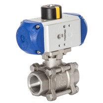
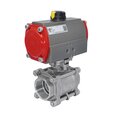
Figure 3: A stainless steel pneumatic ball valve
A valve actuator is a device that is used to remotely control a valve. If it controls a quarter-turn valve, the actuator is known as a quarter-turn actuator. Instead of a manual lever, you can mount an actuator on the valve to automatically and/or remotely control it. Actuators use a power source to generate the torque that is required to operate (rotate) a ball valve. For most actuators, the power source is either pneumatic, electric, or hydraulic (not discussed in this article). The difference in this power source makes different designs, which each have different advantages and disadvantages for certain applications (discussed below). Aside from the torque generating component, an actuator may have other features such as position indicators and manual override.
Pneumatic actuators
Pneumatic actuators control ball valves by the conversion of compressed air energy to mechanical motion. A rotary mechanical motion is required in a ball valve for a 90 degrees turn. Pneumatic actuator ball valves can be single-acting or double-acting. A single-acting pneumatic actuator uses a single compressed air input to turn the valve and a spring to return the valve to the normal position. A double-acting pneumatic actuator has two compressed air inputs to turn the valve and return the valve to the original position.
Operating principle
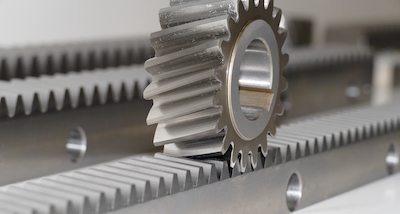
Figure 4: The rack and pinion gear mechanism.
The most common mechanism for a pneumatic actuator for ball valves is the rack and pinion mechanism. This comprises of the rack (a linear gear) and the pinion (a circular gear) (figure 4). The rack is attached to a piston which is pushed by compressed air to achieve linear motion. This linear motion is converted to circular motion by the pinion. The pinion drives the stem of a ball valve to open and close positions.
To control the pneumatic actuator for ball valves, the compressed air is regulated by solenoid valves. Electrical signals from the controller energize the solenoid valve to either open or close positions allowing compressed air to flow through to both piston sides of the pneumatic actuator. The piston pushes the rack which turns the pinion connected to the stem of the ball valve.
Electric actuators
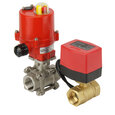
Figure 5: A brass electric ball valve
Electric actuators convert electrical energy into rotary force by the use of an electric motor to turn the ball valve through 90 degrees. They are energy-efficient, clean, and a quiet method of valve control. The electric motor can be powered by an alternating current (AC) or a direct current (DC). It is housed in a robust, compact housing that also contains other components of the actuator such as gearings, limit switches, wiring, etc. The whole assembly is connected to a valve through a compatible connection interface, such as an ISO 5211 standard.
Operating principle
The electric motor generates a torque, which is transmitted by a shaft connected to the valve stem. This rotates the ball valve. To achieve the required torque, a system of gears is connected to the electric motor shaft. The torque capacity is an important specification for selecting an actuator. It must be higher than the required torque (breakaway torque) to turn the ball valve by a certain percentage often specified by the ball valve manufacturer. The breakaway torque is the minimum torque required to turn the ball valve usually in the fully closed or fully open static positions.
The speed of operation (the response time) of an electric actuator is inversely proportional to the torque of the actuator. The gear system defines the relationship between speed and torque. A higher gear ratio would result in more torque but a lower response time.
Electric actuators can be powered from a 12, 24, and 48V direct current and 24, 48, 120, 130, and 240V alternating current. Limit switches are installed to stop the current to the motor when fully closed and open. Electric motors can be used to carry out modulating control. This is used to accurately position the valve at any point between fully opened and fully closed positions (i.e. between 0° and 90°). This is useful for regulating the flow rate through the valve. A positioning circuit board (PCB) is installed in the electric actuator to modulate the electric motor. To learn more about modulation, read our modulating valve article.
Combining an actuator and a ball valve
Although actuators and ball valves are separate components, they are most often used together. Therefore, it is more convenient to get them as a package to ensure conformity. Combining an actuator with a ball valve gives you an automatic ball valve that can be controlled remotely. The actuator and the ball valve have a connection interface to connect them. The connection interface comprises of a shaft, or stem, to connect the valve ball, and a flange to bolt the actuator to the valve. This interface may be brand-specific or standardized to standards such as ISO 5211. You can mount a brand-specific actuator on a compatible brand-specific valve. On the other hand, different ball valves and actuators can be interchanged as long as they follow the same standard, like the ISO 5211 standard.
Comparison between pneumatic and electric ball valves
The following are some of the comparable features of pneumatic and electric ball valves:
Rotation speed
The rotation speed is the speed at which the ball of an actuated ball valve makes a complete rotation (90-degrees). Typically for the same size units, the rotation speed of an electric ball valve is lower than that of a pneumatic ball valve.
Life span
The life span of equipment is the time that the unit is fully functional and operational. Pneumatic ball valves have fewer components and are easier to maintain; hence they have a longer life span than their electric counterparts. Electric actuators have several components that need maintenance, like the electric coil, electronic driver, mechanical actuator, etc.
Precision
Precision, or modulation, is for units that stop at a partially open point (i.e. 20-degrees open) to more accurately regulate the flow. Both pneumatic and electric actuators are precise in operation, but motorized ball valves have higher levels of precision. An electric ball valve is capable of opening and closing by very precise degrees. Pneumatic actuators carry out modulation by controlling the air pressure at the inlet port. Leaks or pressure fluctuations can easily affect the valve’s position. Electrical actuators, on the other hand, use exact electrical control signals to carry out control.
Energy consumption
Energy consumption is the energy required by the actuator to rotate the valve. In comparison, the energy consumption of an electric operated ball valve is less than pneumatic actuated ball valves. In pneumatic actuators, the entire air compression system (compressor, filters, lubricators, power, etc.) accounts for their high energy consumption.
Fail-safe
This is a safety feature designed to automatically open or close a valve in case of a power failure. It is typically easier and cheaper to feature a fail-safe mechanism on a pneumatic ball valve than on a motor actuated ball valve. Pneumatic acting actuators are very common and make use of a spring to return to the base position and are ideal as a fail-safe solution. Electric actuators with a fail-safe mechanism can operate with a battery or a spring and are usually more expensive than the pneumatic solution.
Cost
The cost of a pneumatic ball valve is usually lower than an electric one because the actuator design is less complex. However, this doesn’t take into account the costs of the components of the pneumatic system, such as the compressor, air preparation, pipes, etc. When no pneumatic system is available near the valve, usually electric actuation is preferred. The operation of a pneumatic valve is more expensive in the long run due to the higher energy consumption and energy losses that are a result of generating compressed air.
Position feedback
Position indicators indicate the position of the actuator at any given time. They are usually placed atop the actuator for high visibility. Most pneumatic actuators can be equipped with a limit switch on top for electrical feedback. Many electrical actuators have internal limit switches for position feedback. However, more basic actuators do not have this feature.
Size/torque range
Torque is the rotary force a ball valve requires to turn. Pneumatic actuators offer a much higher torque per unit size than electric actuators. Therefore, for applications requiring a large valve or high torque typically a pneumatic ball valve is a better option.
Hazardous conditions
An electric ball valve has to be NEMA/ATEX certified before it can operate in hazardous conditions. Pneumatic actuators, however, are more widely available with ATEX certification. Also, they neither generate nor are affected by electromagnetic disturbance. Unlike their electric counterparts, pneumatic actuators are not sensitive to wet environments, neither are they subject to overheating.
Comparison table for pneumatic and electric ball valves
This comparison table is for pneumatic and electric ball valves of the same size and is a general comparison. There will be special applications and/or certain designs where this comparison isn’t accurate. The properties can also be used as the selection criteria.
Table 1: Pneumatic vs electric ball valves| Type | Pneumatic ball valves | Electric ball valves |
| Rotation speed | Typically faster. | Typically slower. |
| Life span | Fewer components and easier to maintain, resulting in a higher life span. | Numerous complex components, more affected by wear, making maintenance harder, and typically a reduced life span. |
| Precision | Leaks and pressure fluctuations can cause precision issues. | Precise electrical signals result in precise valve positioning. |
| Energy consumption | The air compression system consumes a lot of energy to deliver the air to the actuator. | Only requires electricity, which has a lower energy consumption than a complete compressed air system. |
| Cost | Lower initial cost, but higher operating cost. | Higher initial cost, but lower operating cost. |
| Fail-safe | Easier and cheaper to have. | More complicated to have. |
| Size/torque range | Have a higher torque to size ratio. | Have a lower torque to size ratio. |
| Hazardous conditions | More suited for rough environments, versions available for NEMA/ATEX environments. | Requires NEMA/ATEX certifications for hazardous environments. |
| Operating conditions | Can operate in high pressure and temperature conditions | Can operate in moderate pressure and temperature conditions |
| Maintainability | Simple mechanism and easy to maintain | A complex mechanism that requires a technical expert |
| Electromagnetic interference | No disturbances | May experience signal disturbances |
| Modulating control | Cannot be used for flow modulation | With a PCB, it can be used for flow modulation |
| Weight | Lightweight | Much heavier |
Application examples for pneumatic or an electric ball valve
- Manufacturing environment: In a moist and rough manufacturing environment often compressed air is readily available. In installations where many large ball and/or butterfly valves are operated (e.g larger than DN 50), pneumatic actuators are often chosen because of the high torque, robustness, and lower material cost.
- Mobile application: A robot that drives around would more likely have electric power than pneumatic, considering the mobility that an electric ball valve will allow.
- Heat exchanger: If there is a power failure, the system still requires cold water to cool any remaining hot water to prevent overheating. In this application, a pneumatic ball valve is better.

