How To Wire a DIN Connector
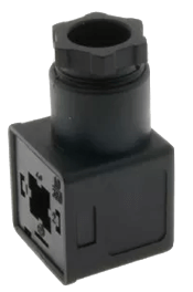
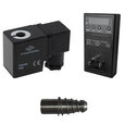
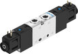
Figure 1: DIN-A connector
The DIN (Deutsches Institut fur Normung) standards define a DIN connector's physical dimensions and electrical characteristics, ensuring compatibility and interchangeability between different manufacturers. This article explores the various configurations of a DIN connector and how to wire a DIN connector to a solenoid valve.
What is a DIN connector
DIN connectors, also known as a solenoid valve connector, are typically circular and feature a range of pin configurations depending on the specific type and application. The DIN 43650 Form A, Form B, and Form C connectors are the most commonly used types for solenoid valve applications. Form A and Form C connectors have two or three pins for the signals plus a ground pin. A Form B connector has two pins for the signals and an additional pin for the ground.
How to wire the DIN connector
Here's a step-by-step guide on how to connect a DIN connector to a device like a solenoid valve:
- Cut the wire: Start by stripping a small portion of the outer insulation of each wire using the wire stripper. Be cautious not to damage the individual conductors inside the cable during this process.
- Identify the pins and wiring mechanism: Identify the pinout of the specific DIN connector. DIN connectors can have different numbers of pins and arrangements, so consult the datasheet or manual to determine the correct pinout and the wiring mechanism (screwed or soldered) for the specific connector. Screwed DIN connectors have screw terminals inside the connector housing, while soldered DIN connectors typically have solder cups or solder pins inside the connector.
- Access the DIN connector plugs: Unscrew the central fixing screw to unassemble the various parts of the DIN connector. This reveals the DIN plug holes to which the cable wires will get attached.
-
Insert the wires: Insert the stripped ends of the wires into the corresponding pin slots.
- For most DIN connectors, there are screw terminals for each pin. Loosen the screws using the screwdriver to create a gap that allows inserting the wire. Connect both poles on the connector to the power supply (the polarity is not important here). Also, ensure to connect the earth or grounding wire.
- Alternatively, solder the wires to the appropriate pins if the pins are designed for soldering connections.
- Secure the wires: Once the wires are in place, tighten the screws. Ensure that the wires are held firmly in place.
- Reassemble the various parts of the DIN housing and tighten the screw at the top.
Note: Positioning the DIN plug with its entry point (opening or orientation of the DIN plug where the cables are inserted) facing downward helps prevent water accumulation and potential damage. Gravity aids in water drainage and minimizes direct exposure to water sources, reducing the risk of water entering the connector. Follow manufacturer instructions for proper installation and orientation.