


Belimo VAV Controllers - How They Work
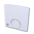
Figure 1: Belimo VAV controller CRA24-B3
A VAV (Variable Air Volume) controller regulates airflow to different zones of a building, optimizing comfort and energy efficiency in an HVAC system. This article focuses on Belimo VAV controllers to demonstrate VAV controllers in general. One Belimo VAV controller is designed to control a single zone. While the controller can manage both supply and exhaust air within that zone, it cannot handle multiple separate zones simultaneously.
Table of contents
- Belimo VAV controller features
- Belimo CRA24-B3 room controller
- Belimo CRA24-B1P 3-step switch VAV controller
- Belimo VAV controller comparison
- Belimo VAV controller installation
View our online selection of room thermostat applications!
Belimo VAV controller features
- Control strategy choice: The user can choose whether to focus on controlling air volume (saving energy) or room temperature (improving comfort).
- Cooling/Heating switch: This feature allows the user to switch between cooling and heating modes as needed.
- Temperature monitoring: The controller monitors room temperature, ensuring it stays within a desired range.
- Override features: Includes kitchen and bathroom overrides (CRA24-B3 model) to manage pressure differences and humidity, enhancing comfort and preventing moisture issues.
- Energy saving and protection modes: Features Energy Hold Off (EHO) for energy conservation during absences and Room Protection (Frost) to prevent freezing at temperatures below 14°C.
- External temperature sensor: Enables connection of an external sensor for more accurate temperature management, particularly useful for exhaust air ducts to calculate and adjust to average room temperature.
Belimo CRA24-B3 room controller
Belimo CRA24-B3 room controller (Figure 1) is equipped with four inputs and three outputs to provide comprehensive control over the indoor environment. The room controller can only control one zone individually.The various inputs and outputs are:
-
Inputs:
- Override signals from kitchen and bathroom environments to manage specific conditions. Belimo VAV controller kitchen/bathroom overrides increase exhaust airflow to address pressure imbalances and humidity in those zones.
- Energy Hold Off (EHO) feature for enhanced energy efficiency.
- External temperature sensor with a specific operating range for accurate temperature readings.
-
Outputs:
- Two variable voltage outputs (2 - 10 V) for controlling supply and exhaust air via damper actuators.
- Versatile heating output compatible with both 2-point (thermal actuator) and 3-point configurations.
Note: Type CRA24-B3(P) functions the same as the CRA24-B3, but with a hidden user interface.
Operating modes
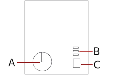
Figure 2: Belimo CRA24-B3 operating modes: Rotary knob for setpoint adjustment (A), status display (B), and mode switch (C).
The rotary knob (Figure 2 labeled A) allows for the manual adjustment of air volume to minimum, a variable range (30 - 70%), or maximum settings, providing precise control over air exchange rates for specific application needs, enhancing both energy efficiency and occupant comfort.
The mode switch (Figure 2 labeled C) allows users to quickly select between predefined operating modes (COMF, MIN, MAX) to set the system's overall performance goal, while the rotary knob provides finer control within those modes. The mode switch can be toggled to operate in one of the following modes:
- COMF (comfort-oriented mode): Maintains a comfortable environment, ideal for regular use.
- MIN (minimum operating mode): Reduces air volume to a minimum and regulates heating to save energy during short absences.
- MAX (maximum operating mode): Increases air volume to a maximum for enhanced air exchange, suitable for events or when increased ventilation is needed.
The status display LEDs (Figure 2 labeled B) operate according to the mode switch configuration - red (max), orange (min), and green (comfort-oriented).
Configuration and service
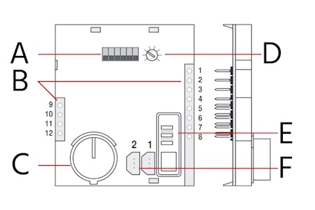
Figure 3: Belimo CRA24-B3 configuration in detail: DIP switch (A), connecting terminals for measuring points (B), rotating knob for control sequence simulation (C), basic set point adjustment for room temperature (D), internal function test (E), and ZTH-GEN/PC-tool connection (F).
- Measuring points for connection terminals (Figure 3 labeled B): Allows for the measurement of all connection terminals' performance, even while the system is operational.
- Internal function test (Figure 3 labeled E): By using the mode switch, a comprehensive internal function test can be initiated, testing the controller's functionality, including its nominal voltage (AC 24 V), with the three LEDs indicating the voltage status.
- Control sequence simulation (Figure 3 labeled C): The rotary knob enables the simulation of connected actuators and control sequences without depending on the room temperature, allowing for setpoint adjustments.
- ZTH-GEN/PC-tool connection (Figure 3 labeled F): Diagnostic sockets 1 and 2 facilitate PP communication with connected Belimo MFT actuators or VAV-Compact controllers, eliminating the need for physical access to these devices.
-
DIP switch (Figure 3 labeled A): The DIP switches on the VAV controller allows the user to customize the controller's behavior to suit the specific needs without needing to access complex software settings.
- P-Band (Proportional Band): This setting determines the controller's sensitivity to temperature changes. Smaller P-Band means the controller reacts more frequently to minor temperature fluctuations. Larger P-Band allows for slightly larger temperature variations before the controller adjusts airflow.
- Control strategy: The user can choose between room temperature and air volume control. Room temperature control focuses on maintaining a set room temperature by adjusting airflow and potentially heating (if applicable). Air volume control prioritizes a specific airflow range (30-70%) regardless of temperature.
- Control sequence: This defines the order in which heating or cooling is activated (not applicable for all models).
- Reset function: Determines how the controller reacts after reaching the maximum setpoint (usually temperature). The controller immediately attempts to reduce airflow/heating upon reaching max setpoint in the default setting. In the second mode, the controller waits for 1 hour before adjusting airflow/heating after reaching max setpoint (may be useful to prevent rapid switching).
- Max temperature monitoring: Enables or disables monitoring of a maximum temperature limit.
- Heating output definition: This configures the controller for a specific type of heating actuator (2-point or 3-point).
Table 1: Belimo CRA24-B3 DIP switch configuration
| DIP switch | Default settings | On functionality |
| 1 | P-Band normal | P-Band wide |
| 2 | Air volume control strategy | Room temperature control strategy |
| 3 | Control sequence for air cooling | Control sequence for air heating |
| 4 | Reset MAX → COMF Off | Reset MAX → COMF 1 h |
| 5 | Max temp monitoring Off | Max temp monitoring On |
| 6 | Definition of heating output (ao3) 2-point actuator | Definition of heating output (ao3) 3-point actuator |
Figure 4: Close-up of DIP switches. DIP switch 4 is OFF and ON in the top and bottom images respectively.
Wiring diagram
Figure 5: Belimo CRA24-B3 vav controller wiring diagram
Inputs
- 3 ai1: Connection for an external temperature sensor, allowing the system to adjust operations based on the detected ambient temperature.
- 4 di2: Input for a kitchen override signal, which adjusts the system to compensate for air pressure changes caused by kitchen appliances.
- 12 di3: Input for a bathroom override signal, enabling the system to increase exhaust air volume to quickly remove humid air.
- di1: Designated for the Energy Hold Off (EHO) function, which reduces energy consumption during periods of inactivity by adjusting air volumes and heating settings.
Outputs
- 6 ao1 & 11 ao2: These are system outputs for the VAV controller managing supply and exhaust air, respectively. They regulate air volume to maintain desired environmental conditions.
- 9/10 ao3: A 2-point / 3-point output for heating control, allowing the system to adjust heating levels based on the room's temperature requirements.
Other connections
- 7 PP1 & 8 PP2: Diagnostic sockets for the VAV controllers of supply and exhaust air, respectively. These connections are used for system diagnostics and troubleshooting.
Not used
- 5: This position is reserved but not currently utilized in the system configuration.
Belimo CRA24-B1P 3-step switch VAV controller
Figure 6: Belimo CRA24-B1P VAV controller
The Belimo CRA24-B1P VAV controller is simple and optimized for use in controlled apartment ventilation systems. This controller allows for precise control over air flow, ensuring optimal air quality and comfort by adjusting the levels of air entering or leaving the space. It features a single analogue output (ao1) compatible with either a VAV unit or a damper actuator, enabling control over the supply or exhaust air devices.
The CRA24-B1P VAV controller is easy to use, with a button on the front control panel that allows users to manually switch between different operating modes. In comparison to the more complex CRA24-B3, the CRA24-B1P is designed for simpler HVAC systems. It offers basic adjustments with its 3-step switch, suitable for settings that require simple control over the air device's speed or intensity. Unlike the CRA24-B3 or CRA24-B3P, the CRA24-B1P does not support simultaneous control of supply and exhaust air or the management of a heating valve.
Operation and configuration
By using a push-button along with a concealed rotary knob located under the controller's front panel, users can pre-select and adjust the air volume to one of three settings: minimum, variable (with a range of 30 to 70%), or maximum.
{IMAGE"belimo-vav-configuration2.jpg}Figure 7: Belimo CRA24-B1P configuration: rotating knob for setpoint adjustment (A), connecting terminals for measuring points (B), internal function test (C), and ZTH-GEN / PC-tool connection (D),
Wiring diagram
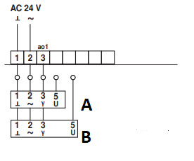
Figure 8: Belimo CRA24-B1P wiring diagram: supply air VAV controller (A) and extract air VAV controller (B)
Belimo VAV controller comparison
Table 1: Belimo VAV controller comparison table
| Feature/Functionality | Belimo CRA24-B3 | Belimo CRA24-B1P |
| Control type | Advanced control with multiple inputs and outputs | Simplified control with a 3-step switch |
| Operating modes | Multiple predefined and customizable operating modes | Manual switch between different modes |
| Heating valve control | Some models can control heating valves | Not supported |
| Energy efficiency features | Advanced features like Energy Hold Off (EHO) and Room Protection (Frost) | Basic |
| Inputs and outputs | Four inputs and three outputs for comprehensive control | Single analogue output (ao1) |
| Special settings for Kitchens/bathrooms | Overrides for kitchen and bathroom environments | Not available |
| User interface | User interface with more complex settings | Simple button on the front panel |
| Suitability | Complex HVAC systems requiring detailed control and customization | Simpler HVAC systems requiring basic control |
| Simultaneous control of supply and exhaust air | Supported | Not supported |
Belimo VAV controller installation
- Accessing the PCB:
- Begin by removing the cover of the housing.
- Gently pull the housing's wall outward to create space.
- Carefully extract the PCB for maintenance or inspection.
- Reattaching the rotary knob:
- If the rotary knob has been detached, start by inserting it halfway into its slot, then rotate it clockwise until it reaches the end stop.
- Remove the knob again, adjusting its position so the cam aligns flush with the left-hand end stop.
- Finally, insert the rotary knob fully into position.
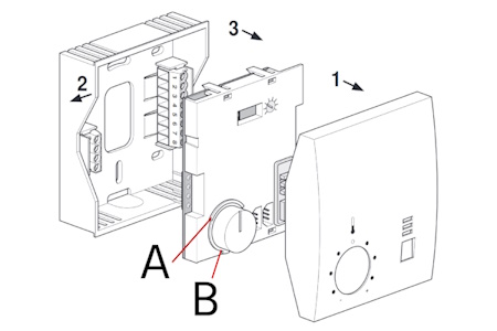
Figure 9: Belimo VAV controller installation showing left-hand end stop (A) and cam (B)
