


How To Install a Mechanical Pressure Switch
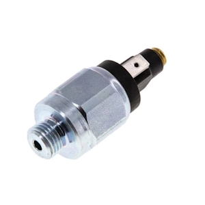
Figure 1: A steel mechanical pressure switch
Understanding the proper installation of a mechanical pressure switch is essential for maintaining system integrity and ensuring operational safety in various industrial applications. This article discusses the design and operation of mechanical pressure switches, guiding readers through the step-by-step installation process and providing insights into the removal procedure.
Table of contents
- Mechanical pressure switch operating principle
- Installing a mechanical pressure switch
- Removing a pressure switch
View our online selection of mechanical pressure switches!
Mechanical pressure switch operating principle
A mechanical pressure switch works by turning pressure changes into electrical signals. Inside the switch, the piston moves when the pressure goes up or down. This movement is controlled by a set screw that can be set to react at certain pressure levels. When the piston moves, it triggers another part called a microswitch. The microswitch either starts or stops the flow of electricity, which affects the system, like turning on a pump or setting off an alarm. The switch connects to the system at a point called the connection port, and it's important that this connection doesn't leak. In short, the switch senses pressure changes and sends an electrical signal to keep the system running safely and correctly. Read our overview article on pressure switches to learn more about this device.
Installing a mechanical pressure switch
Before installation
- Before installing a mechanical pressure switch, ensure the following:
- The switch is suitable for the system's media. For example, some piston pressure switches might be unsuitable for gaseous media, such as oxygen. Learn more in our chemical resistance guide.
- Read and understand the manufacturer's installation instructions
- Ensure that the system is depressurized and the power supply is turned off to avoid any accidents
- Wear appropriate personal protective equipment (PPE) such as gloves and safety glasses
Tools and materials needed
- Mechanical pressure switch
- Teflon tape or pipe thread sealant
- Adjustable wrench or set of wrenches
- Pipe dope (optional)
How to install
Installing a mechanical pressure switch into a piping system is a critical task that ensures the system operates within safe pressure limits. Here is a step-by-step guide on how to install a mechanical pressure switch:
- Select the installation point: Choose a point on the piping system where the pressure switch can be easily accessed for maintenance and where it will accurately measure the system pressure. This is typically on or near the pump or in a place where the pressure is representative of the system's operating pressure.
- Prepare the threaded connection: If the pressure switch has a threaded connection, wrap Teflon tape around the threads in a clockwise direction to ensure a good seal. Alternatively, apply pipe thread sealant (pipe dope) to the threads.
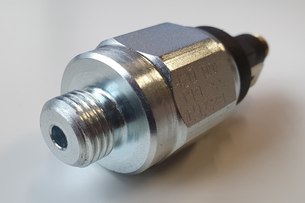
Figure 2: Male threaded connection on a mechanical pressure switch
- Gasket sealing: Stainless steel and copper gaskets are other common sealing methods for these pressure switches. These seals are available in flat or profile rings. Profiled rings are preferred because they can rotate 1/2 revolution further, allowing the pressure switch to mount more accurately.
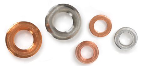
Figure 3: Flat and profiled seal rings.
- Install the pressure switch: Thread the pressure switch into the chosen installation point. Hand-tighten the switch and then use an adjustable wrench to secure it in place. Be careful not to over-tighten, as this could damage the threads or the switch housing.
-
Connect the electrical wiring:Refer to the manufacturer's wiring diagram before wiring a pressure switch. Typically, there will be two or three terminals: one for the power supply, one for the load, and possibly a ground terminal. Connect the wires accordingly, ensuring that all connections are tight and secure.
- Note: If not familiar with electrical systems, it is recommended to hire a licensed electrician for this step.
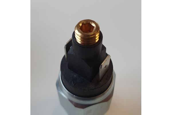
Figure 4: Electrical connection and adjustment screw for a mechanical pressure switch.
- Set the pressure limits: Adjust the high and low pressure limits according to the system's requirements. This is usually done by turning adjustment screws on the switch. Consult the manufacturer's instructions for specific details on setting the pressure limits.
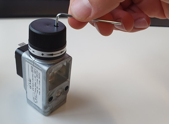
Figure 5: For this switch, the adjustment knob needs to be unlocked with a hex key.
- Test the pressure switch: Once the pressure switch is installed and wired, slowly re-pressurize the system and check for leaks around the switch. Observe the switch's operation to ensure it activates and deactivates at the correct pressures.
- Secure the pressure switch: If the switch is not already mounted, secure it to a wall or panel to prevent movement, which could lead to wiring damage or inaccurate pressure readings.
- Final inspection: Perform a final inspection to ensure that all connections are secure and that there are no leaks. Verify that the electrical connections are properly insulated and that the switch operates as intended.
- Document the installation: Record the installation details, including the pressure switch model, settings, and date of installation, for future reference and maintenance.
Removing a pressure switch
When replacing a pressure switch, the removal process is opposite of the installation process. Ensure that the system is depressurized before starting. Also, sealing rings are often for one-time use; use a new sealing ring when installing a new mechanical pressure switch.
