


HVAC Thermal Energy Meter - How They Work
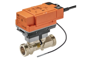
Figure 1: A Belimo thermal energy meter for HVAC systems
HVAC thermal energy meters enable precise monitoring and management of energy use and contribute to environmental sustainability by reducing greenhouse gas emissions. These energy meters are pivotal in optimizing the efficiency and performance of heating, ventilation, and air conditioning systems across various applications, from centralized heating in large buildings to solar thermal systems. Additionally, they ensure fair energy billing, extend the lifespan of HVAC systems, and aid in regulatory compliance. With their critical importance in diverse settings and the technical considerations involved in their design, installation, and selection, understanding HVAC thermal energy meters is essential for anyone looking to enhance HVAC system efficiency and performance.
View our online selection of HVAC thermal energy meters!
Table of contents
- Why HVAC thermal energy meters are important
- Applications
- Thermal energy meter design
- Installation parameters
- Selection criteria
- FAQs
Why HVAC thermal energy meters are important
HVAC thermal energy meters are important because they help monitor and manage the energy use of heating, ventilation, and air conditioning systems. They offer several benefits:
- They make the HVAC system more energy-efficient, which saves money.
- They help reduce the environmental impact by lowering greenhouse gas emissions.
- They improve the performance of the HVAC system and can extend its lifespan.
- They ensure fair billing in buildings with multiple users by charging based on actual energy use.
- They provide necessary data for meeting energy regulations and reporting on energy-saving efforts.
Applications
HVAC thermal energy valves are found in a wide variety of applications and systems:
- Centralized heating systems: Used in large buildings or campuses to distribute heat from a single source.
- Cooling and refrigeration systems: Including central air conditioning systems in commercial and residential buildings.
- Radiant floor heating systems: Where thermal energy flow meters help manage the distribution of heat across different zones.
- Industrial process systems: Where precise temperature control is critical for manufacturing processes.
- Geothermal heat pumps: Utilizing the earth's stable temperature for heating and cooling purposes.
- Solar thermal systems: Harnessing solar energy to provide heating or contribute to hot water systems.
- District heating and cooling networks: Supplying multiple buildings or an entire community from a central plant.
- Heat recovery ventilation systems: Recovering waste heat from exhaust air to preheat incoming fresh air.
- Hydronic systems: Using water as a heat-transfer medium in heating and cooling systems.
- Chilled beams and ceilings: Passive or active systems used primarily for cooling and ventilation in commercial buildings.
Thermal energy meter design
Despite the diversity in models and brands, certain design aspects are universally crucial for a thermal energy flow meter's function. These core design features ensure accurate, reliable measurements and the efficient operation of HVAC systems.
Core components
At the heart of every HVAC thermal energy flow meter are several key components that work together:
- Sensors: Two temperature sensors are necessary for the design; typically, one is placed at the supply line and one at the return line. These sensors measure the temperature of the fluid (usually water or a water-glycol mixture) entering and exiting the HVAC system, which is essential for calculating thermal energy transfer.
- Flow sensor: The flow sensor measures the fluid's rate. This component can vary in design, with some meters using ultrasonic, turbine, or electromagnetic sensors to capture flow data. Learn more in our flow meter types article.
- Calculator: The calculator is part of the sensor module and processes input from the temperature and flow sensors to calculate the thermal energy flow using the formula Q = ƒ(V, ΔT), where Q is the thermal energy, V is the volume flow rate, and ΔT is the temperature difference between supply and return lines.
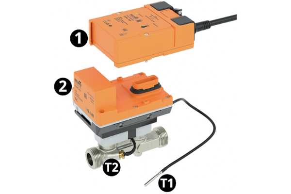
Figure 2: A Belimo HVAC thermal energy meter with components: logic module which connects the thermal energy meter to the power supply (1), sensor module which houses the calculator and measuring system (2), external temperature sensor (T1), and integrated temperature sensor (T2).
Material
The choice of materials for constructing HVAC thermal energy flow meters is critical for durability, accuracy, and compatibility with the system's operating environment:
- Sensor materials: Often made from stainless steel or other corrosion-resistant metals, the sensors must withstand constant contact with the fluid without degrading or altering its properties.
- Housing: The meter's housing is typically constructed from robust materials like brass or stainless steel, offering resistance to physical and chemical damage over time.
Communication and integration
Modern HVAC thermal energy flow meters are designed with integration and communication in mind:
- Output signals: To facilitate easy integration with building management systems (BMS), flow meters produce output signals (analog or digital) that represent the measured thermal energy. This allows for real-time monitoring and control.
- Connectivity: Many models feature connectivity options such as Modbus, BACnet, or wireless protocols, enabling remote data access and system adjustments.
Installation parameters
This section provides an overview of installation instructions for a Belimo thermal energy meter to provide general information on installing thermal energy meters. Before installing a thermal energy meter, thoroughly review the manufacturer's documentation on the installation process.
- Flow direction: Flow through the thermal energy meter is one way only, marked by an arrow on the outside of the device.
- Prevent cavitation: The output pressure must be at least 1 bar at maximum flow and temperatures up to 90 °C to prevent cavitation. At temperatures of 120 °C, the pressure at the output must be at least 2.5 bar.
- Connection to pipe: The thermal energy meter is installed between two pipe connectors.
- Sensor installation: In the case of the Belimo energy meter, one sensor is mounted to the sensor module, and one sensor is installed using a thermowell either upstream or downstream of the thermal energy meter.
- Power supply: Supply the thermal energy meter with the necessary power supply. For example, the Belimo thermal energy meter requires 24 V either DC or AC.
- Installation location: As seen in Figure 4, there are acceptable and unacceptable installation locations for a thermal energy meter.
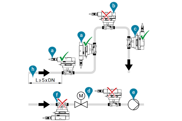
Figure 3: There are several considerations for an optimal location to install a thermal energy meter. Acceptable installation positions (A) and (C) in a closed system. Do not install at the top of a pipe system (B) or air can get trapped in the meter. A straight run before the energy meter (H) is necessary. Do not install upside down (F) or directly after a control valve (D) or in front of a pump (E).
- Installation orientation: As seen in Figure 5, it is acceptable to tilt the flow meter up to 90° away from the upwards vertical direction.
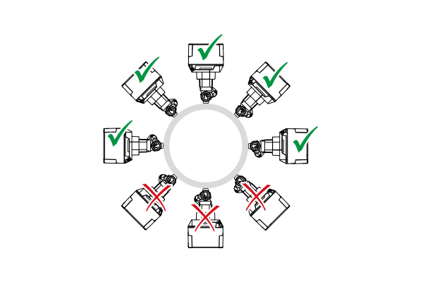
Figure 4: The allowable and unallowable meter tilt during installation.
Selection criteria
- Connection size: Select a connection size that matches the system it will connect to.
- Pipe connection: Determine if the connection is threaded (e.g., NPT, BSP) or welded.
- Maximum thermal output: The maximum thermal output indicates the highest amount of thermal energy transfer (often expressed in kilowatts, megawatts, or other units of power) that the meter can accurately record within its designed operational parameters.
- Kv value: The Kv value indicates the flow rate through the valve. Learn more in our Kv calculator article.
- Electrical data: Consider the energy meter's nominal voltage (AC or DC), voltage range, power consumption, and how it connects to the power supply.
- Data bus communication: Determine how the energy meter will communicate with the system's control center, e.g., BACnet IP, Modbus TCP, and MP-Bus
- Application: Understand if the energy meter will work with water or a water-glycol mixture.
- Materials: Stainless steel and brass are common body materials for wetted parts and EPDM for seals.
-
Safety data: Determine the thermal energy meter's safety data:
- Protection class IEC
- Quality standard, e.g., ISO 9001
- Ambient temperature
- Fluid temperature
- Storage temperature
FAQs
What is an HVAC energy meter?
An HVAC energy meter measures and monitors the energy consumption of heating, ventilation, and air conditioning systems to optimize efficiency.
How does an ultrasonic thermal energy meter work?
It measures fluid flow using sound waves and calculates energy use based on temperature changes.
