


How to Size and Select a Modulating Control Valve
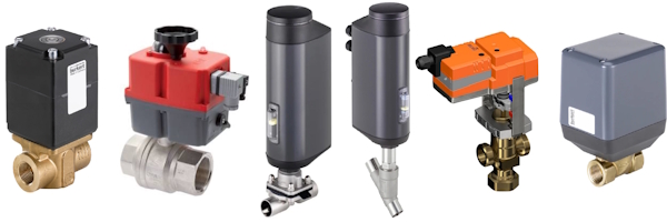
Figure 1: A variety of modulating control valves, from left to right: proportional solenoid valve, modulating ball valve, electric diaphragm valve, electric angle seat valve, electric globe valve, and electric disc valve.
Accurate modulating control valve sizing is a necessary requirement for ensuring process stability, maximizing energy efficiency, and minimizing damage to equipment. Valves that are too large or too small can cause noise, cavitation, and early failure.
To size a modulating control valve, calculate the required flow coefficient (Kv or Cv), verify allowable pressure drop, and choose a valve type (globe, ball, etc.) that operates between 20-80% open at normal flow.
Table of contents
- The fundamentals of control valve sizing
- Control valve sizing guide: step-by-step
- Types of modulating control valves
The fundamentals of control valve sizing
This section focuses on fundamental concepts that are necessary to understand in order to correctly size a control valve. If these concepts are too basic, skip ahead to the "Control valve sizing guide: step-by-step" section.
The flow coefficient: Kv and Cv
The flow coefficient (Kv or Cv) is an important metric used to quantify a valve's capacity to pass fluid under standardized conditions.
- Kv: Represents the flow rate of water in cubic meters per hour (m³/h) at a pressure drop of 1 bar across the valve.
- Cv: Commonly used in the United States, Cv represents the flow rate of water in gallons per minute (GPM) at a pressure drop of 1 psi across the valve.
If the flow coefficient is underestimated and the valve is undersized, the system may experience excessive pressure drop and insufficient flow, leading to poor performance. If it is overestimated and the valve is oversized, control accuracy is reduced and the valve may operate mostly near closed position, causing instability and wear.
System pressure dynamics and valve authority
A modulating valve's performance depends on how its pressure drop compares to the rest of the system. This interaction is known as valve authority (β). A high authority ensures that a change in the valve’s position produces a significant and predictable change in the system flow rate, leading to better control stability.
The system differential pressure is the driving force for flow. This total pressure is divided between the control valve (ΔPV) and the remaining elements in the circuit (ΔPC). These elements may include pipes, fittings, strainers, etc.
Valve authority is a dimensionless ratio that measures how much influence the valve has over the total flow rate compared to the fixed resistance of the rest of the circuit. It is mathematically defined as the ratio of the pressure drop across the fully open control valve (ΔPV) to the total pressure drop across the entire circuit when the valve is fully open (ΔPV+ΔPC).
Example
If the fully open valve has a pressure drop ΔPv = 2 bar and the rest of the system contributes ΔPc = 3 bar, then:
β = ΔPv ÷ (ΔPv + ΔPc) = 2 ÷ (2 + 3) = 0.4 → 40% authority.
This falls within the recommended 35–75% range.
Critical selection window
For pressure-dependent control valves, sizing requires balance between the demands of control stability and energy consumption. An undersized valve will have a high valve authority, resulting in excellent control but high energy consumption as the system overcomes the valve's resistance. Oversized valves save energy but make flow control unstable.
The optimal valve authority range is 35% to 75%. Selecting a valve within this window ensures sufficient pressure drop at the control valve without excessive energy usage. When absolute precision is necessary, selecting a valve with authority 75% and above is best, even though there is an energy trade-off.
Table 1: Valve authority range: control quality, energy consumption, and sizing consequence
| Authority range (β) | Control quality | Energy consumption | Sizing consequence |
| 0% - 25% | Unstable to poor | Very low | Severe oversizing; on/off action near shut-off position. |
| 35% - 75% | Fair to good | Compromised/Balanced | Optimal modulating range |
| 75% - 100% | Good to excellent | High | Highly reliable control, but often requires costly pressure sacrifice. |
Pressure independent solution
The challenges of valve authority calculations and energy penalties are mostly solved by pressure independent control valves (PICVs). With a minimum differential pressure maintained for operation, a PICV maintains a constant flow rate despite changes in the differential pressure across it. Because this type of valve removes the influence of system pressure fluctuations, it has an inherent valve authority of 100% and achieves high energy efficiency.
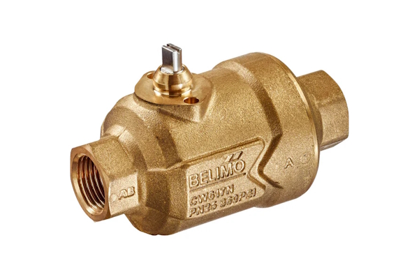
Figure 2: A pressure independent zone valve for HVAC
Inherent flow characteristics
A control valve's inherent flow characteristic defines the relationship between the percentage of valve stem travel and the resulting percentage of flow rate. This definition assumes a constant differential pressure across the valve.
Table 2: Inherent flow characteristics
| Inherent characteristic | Definition | Gain behavior | Preferred application |
| Quick opening | Maximum flow achieved quickly. | High gain at low stroke. | On/Off or batch loading. |
| Linear | Flow rate proportional to stem travel. | Constant gain across stroke. | Constant pressure systems. |
| Equal percentage | Flow changes by a constant percentage of current flow. | Exponential gain (low at start, high at end). | Systems with high and variable pressure drop. |
Note: Gain is the ratio of output change to input change
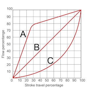
Figure 3: Theoretical depictions of inherent flow characteristics: quick opening (A), linear (B), and equal percentage (C)
Equal percentage valves are preferred in most modulating applications because real systems rarely maintain constant pressure drop. As the valve closes, the system pressure drop across the valve increases. The equal percentage characteristic compensates for this effect, producing an approximately linear overall system response.
Rangeability and turndown ratio
Rangeability (R) is a property of the valve body and trim design. It is defined as the ratio of the maximum controllable flow (Qmax) to the minimum controllable flow (Qmin) when pressure drop is constant (i.e., measured in a lab setting). For example, a globe valve with rangeability of 50:1 can reliably modulate flow from 100% to 2% of its maximum capacity.
Turndown ratio (TDR) is the operational measure of performance, in other words, how the valve performs at modulating flow when not in a controlled laboratory setting. It is the ratio of the maximum usable flow to the minimum controllable flow. The TDR is always less than or equal to the valve's theoretical rangeability.
The resolution of the actuator paired with the control valve has the most influence on the turndown ratio. If a valve with high rangeability is paired with an actuator with low resolution, the valve's opening mechanism (e.g., ball or disc) is unlikely to be positioned precisely where it should be. This will cause the actuator to "hunt" for the correct position, which overcycles the valve. Ultimately, this can drop the turndown ratio to as low as 3:1.
Control valve sizing guide: step-by-step
Step 1: Gather key sizing parameters
Before any sizing calculations can be done, it's necessary to understand the key sizing parameters:
- Fluid properties: Identify the medium (liquid, gas, or steam), its specific gravity, viscosity, vapor pressure, and critical pressure.
-
Flow requirements: Maximum flow (Qmax), normal flow (Qnorm), and minimum flow (Qmin).
- Qmax is necessary for calculating the necessary Kv (explained above)
- Qmin is necessary for checking the valve's turndown capability (explained above)
- Pressure and temperature: Upstream and downstream absolute pressure, or pressure drop for Qmax. Operating temperature is also required.
- Design constraints: Desired system authority (β) (explained above) and inherent flow characteristic (often equal percentage).
Step 2: Determine allowable pressure drop
When sizing a control valve, you need to know how much pressure drop it can safely take. Too much pressure drop can cause cavitation, flashing, noise, erosion, or simply limit the valve’s flow capacity.
The allowable pressure drop is determined by the lowest of three values:
- Available system pressure drop: The difference between upstream and downstream pressures.
- Choked pressure drop: The hydraulic/flow limit: cavitation in liquids, sonic velocity in gasses.
- Valve maximum differential pressure rating: The mechanical strength limit specified by the manufacturer.
IEC 60534 provides calculation methods to predict choked flow using parameters such as the valve’s pressure recovery factor (FL) and fluid properties like vapor pressure (Pv) and critical pressure ratio factors (FF, xT).
Important distinction:
- The maximum ΔP rating is a mechanical limit.
- The choked ΔP is a hydraulic limit.
- The allowable ΔP for sizing is whichever is lower under your service conditions.
Example 1: Water
- Upstream pressure: 10 bar
- Downstream pressure: 4 bar
- Fluid: Cold water (Pv ≈ 0 bar)
- Valve rating: 6 bar max ΔP
- Valve recovery factor: FL=0.9, FF = 0.96
Step 1: Available ΔP
Step 2: Choked ΔP
For liquids, IEC 60534 gives:
Where:
- P1 = upstream absolute pressure
- Pv = fluid vapor pressure
- FF = liquid critical pressure ratio factor (~0.96 for water)
- FL = valve pressure recovery factor
Applying:
Step 3: Compare
- Available ΔP = 6 bar
- Choked ΔP = 8.1 bar
- Mechanical rating = 6 bar
Therefore, the allowable ΔP = 6 bar (limited by system and rating)
Example 2: Air
- Upstream pressure: 7 bar
- Downstream pressure: 2 bar
- Fluid: Air
- Valve rating: 10 bar max ΔP
- Valve recovery factor: FL = 0.85
- Gas critical pressure ratio factor: xT = 0.7
Step 1: Available ΔP
Step 2: Choked ΔP
For gasses:
Step 3: Compare
- Available ΔP = 5 bar
- Choked ΔP = 3.6 bar
- Mechanical rating = 10 bar
Therefore, the allowable ΔP = 3.6 bar (limited by sonic choking)
Step 3: Calculate flow coefficient (Kv or Cv)
Once the allowable pressure is established, the flow coefficient can be calculated.
Table 3: Calculate flow coefficients for liquids and gasses
Liquids |
Kv |
|
|
| Cv |
|
||
Gasses |
Kv |
|
|
| Cv |
|
Step 4: Preliminary valve selection and stroke range
The calculated flow coefficient is used to select the initial valve size and trim combination. To ensure optimal performance, the valve should be sized so its operation stays within a usable stroke range. During operation, the valve should avoid operating near the fully-closed position or the fully-open position. A good estimate is that the valve's stroke travel should be between 60% - 80% during max flow and no less than 20% during minimum flow.
If the calculated flow coefficient leads to an oversized valve, the valve will be forced to operate at the low end of its stroke (e.g., below 20%) to throttle the flow accurately. This operation drastically compromises the turndown ratio, often dropping it to 3:1 or less, leading to high gain instability and cycling. Furthermore, sizing the valve to be significantly less than half the pipe size is generally avoided to prevent unnecessary turbulence and localized pressure losses outside the control element.
Turndown check
After preliminary selection, the minimum flow rate (Qmin) is checked against the manufacturer’s characteristic curve to ensure the corresponding stroke percentage does not fall below 10%. If the valve is operating too close to the seat at minimum flow, a smaller valve may be required to shift the operating range up into the stable control band (20%-80%).
Types of modulating control valves
Once the required control valve flow coefficient has been calculated, the next step is to choose the most suitable valve type for the application. While the control valve size is critical, the valve’s construction, flow characteristic, and compatibility with the medium are equally important. Below are key considerations for common modulating valve types:
Actuated globe valve
The globe valve remains the most versatile option for precise throttling. With excellent rangeability and predictable flow characteristics, it is often selected when high accuracy is required. The globe valve Cv and globe valve size should be carefully matched to the system’s calculated flow requirements, keeping the control valve size vs line size relationship in mind. In many cases, a globe valve is intentionally smaller than the line size to achieve better control authority.
Actuated disc valve
Disc valves are compact and reliable, often used in applications requiring moderate control performance with lower cost. Available in a variety of disc valve sizes, they are best suited where space is limited and where extremely fine modulation is not required.
Actuated angle seat valve
Angle seat valves are valued for their durability and high cycle life, especially in steam and aggressive media service. An angle seat valve's ability to handle frequent actuation makes them a strong choice for clean industrial processes.
Actuated diaphragm valve
Diaphragm valves are particularly effective in handling corrosive fluids, slurries, or hygienic applications. Their diaphragm valve Cv and diaphragm valve Kv value must be carefully compared to the required duty point, as they typically have lower flow capacities than globe or ball valves. Available in a range of diaphragm valve sizes, they are often chosen when media compatibility is the overriding factor.
Modulating ball valve
Ball valves with characterized trims provide good control performance while maintaining a compact design. A properly selected port size of control valve allows them to achieve both tight shutoff and stable modulation. They are often selected for HVAC, water, and general utility systems where high flow capacity is required.
Proportional solenoid valve
Proportional solenoid valves offer fast response and compact form, making them ideal for low-flow applications or systems requiring frequent adjustment. They are generally available in smaller sizes and are best suited where precise low-flow modulation is more important than large flow capacity. Learn more in our proportional solenoid valve overview article.
Pressure independent control valve (PICV)
Pressure independent control valves combine a modulating control valve with an integrated differential pressure regulator. This design automatically compensates for changes in system pressure, maintaining a constant flow rate regardless of upstream or downstream fluctuations. By eliminating the need for manual balancing, PICVs simplify commissioning and significantly improve energy efficiency in variable flow systems.
Table 4: Real world use cases for modulating control valves
| Valve type | Common applications |
Actuated globe valve |
Temperature control in heat exchangers or jacketed reactors |
| Steam flow regulation in power generation or process heating systems | |
| Pressure control in water treatment plants | |
Actuated disc valve |
Cooling water control in industrial chillers or condensers |
| Air handling units where moderate control precision is sufficient | |
| General-purpose fluid distribution systems with frequent open/close cycles | |
Actuated angle seat valve |
Steam control in sterilization or pasteurization systems |
| Hot water or condensate control in CIP (clean-in-place) systems | |
| Process lines carrying mildly corrosive or viscous fluids | |
Actuated diaphragm valve |
Chemical dosing and acid/alkali handling |
| Biopharmaceutical or food production lines requiring sterile operation | |
| Slurry or abrasive media control in mining and wastewater processing | |
Modulating ball valve |
Chilled and hot water control in HVAC systems |
| Cooling tower bypass or condenser water regulation | |
| Industrial utility systems where robust, low-maintenance control is needed | |
Proportional solenoid valve |
Precise gas or air control in laboratory or analytical equipment |
| Dosing control in packaging or beverage filling lines | |
| Microfluidic or medical device flow regulation | |
PICV |
Zone control in variable flow HVAC systems |
| Fan coil or air handling unit supply lines | |
| Hydronic heating and cooling networks requiring automatic balancing |
FAQs
What is valve authority, and why is it important?
Valve authority is the ratio of pressure drop across a valve to total system drop. Higher authority (≥0.5) improves control accuracy and stability.
What is a modulating control valve?
A modulating valve adjusts fluid flow continuously using an actuator and control signal to maintain target flow or pressure.


