


Guiding Units For Pneumatic Cylinders
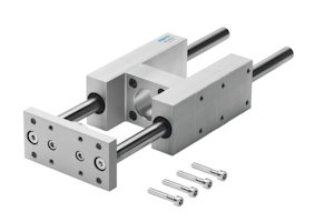
Figure 1: A Festo FENG pneumatic cylinder guide unit
A guide unit for pneumatic cylinders provides additional support and alignment to the piston rod of a pneumatic cylinder, ensuring smoother and more precise linear motion. They help manage and distribute the load more effectively, preventing the piston rod from bending or deflecting under heavy loads. This is particularly important in applications requiring high accuracy and repeatability and where the cylinder is subjected to side or off-center loads. By providing better alignment and reducing side loads, guide units minimize the wear and tear on the cylinder's seals and bearings, thereby extending the lifespan of the pneumatic cylinder.
Design
Guiding units for pneumatic cylinders are designed to fit around the cylinders. The piston rod end attaches to the guide unit's coupling (Figure 2 labeled B). When the piston actuates, it pushes or pulls the yoke plate (Figure 2 labeled A). The yoke plate is also attached to two guide rods (Figure 2 labeled D), which help redistribute the load across the entire guide unit. The guide rods are positioned in guides (Figure 2 labeled C) or bearing blocks, which also contain the bearings, which can be either ball bearings (Figure 2 labeled E) or plain bearings (figure 2 labeled F).
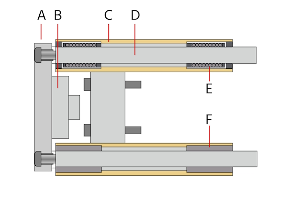
Figure 2: Components of a guiding unit: yoke plate (A), coupling (B), guide (C), guide rods (D), ball bearing guide (E), and plain bearing guide (F). Note that a guide unit has ball bearing guides OR plain bearing guides, not one of each.
Ball bearings vs plain bearings
Consider the following if selecting between guide units with ball bearings and units with plain bearings:
- Precision: Guide units with ball bearings typically offer more precision than plain bearing units.
- Friction: Ball bearings cause less friction than plain bearings, making them more suitable for high-cycle operations.
- Linear motion: Ball bearing guide units have smoother linear motion than plain bearing guide units.
- Load tolerance: Plain bearing guide units can tolerate higher loads.
- Impact: Plain bearing guide units can also tolerate higher shock impacts, making them suitable for heavy-duty applications.
- Cost-effective & extreme environments: Because they have fewer moving parts, plain bearings are typically less expensive and can operate in harsher environments with contaminants.
- Noise: Plain bearings are less noisy than ball bearing guide units.
Learn more about these two types of bearings in our bushing vs bearings article.
Installation
Attaching a guiding unit to a pneumatic cylinder is a critical process that ensures the smooth and precise operation of the system. Here’s a step-by-step guide on how to properly attach a guiding unit to a pneumatic cylinder:
- Preparation: Clean the work area and components so debris and contaminants will not interfere with the installation. Verify that the guiding unit, pneumatic cylinder, and mounting kit are compatible.
- Gather tools and components: Ensure all necessary tools are within reach, including the pneumatic cylinder, guiding unit, mounting kit (brackets, bolts, nuts, washers), and any specific tools the manufacturer recommends.
- Positioning: Place the pneumatic cylinder and guiding unit in the desired configuration. The cylinder's piston rod must be aligned with the guiding unit's path to prevent binding and ensure smooth operation.
- Attach mounting brackets: Attach the brackets to the guiding unit first. These brackets hold the guiding unit securely and align it with the pneumatic cylinder. The mounting kit comes with bolts and nuts necessary to attach the brackets. Do not overtighten the bolts and nuts.
- Align pneumatic cylinder: Line up the pneumatic cylinder's mounting holes with those on the guiding unit brackets. Insert the piston rod into the guiding unit, ensuring it moves freely without resistance.
- Secure cylinder: Attach the pneumatic cylinder to the guiding unit brackets. Again, do not overtighten nuts and bolts. It is useful to start by loosely fitting nuts and bolts so adjustments can be made if necessary. When satisfied, gradually tighten in a crisscross pattern.
- Testing: Before putting the system into full operation, perform a test run. Slowly actuate the pneumatic cylinder to observe the motion of the piston rod within the guiding unit. Ensure that the movement is smooth and free of any binding or excessive friction.
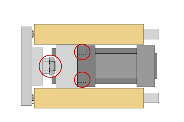
Figure 3: The piston rod end connects to the cylinder guiding unit via a female threaded connection and bolts (circled in red)
Applications
Guide units are used when the piston rod requires additional support to prevent bending or deflecting under load. This is important in high-force or high-speed, automatic operations.
- Automation and robotics: Guide units are widely used in automated systems and robotic arms to ensure precise and repeatable movements.
- Material handling: In conveyor systems and other material handling applications, guide units help in managing loads and ensuring smooth operation.
- Packaging machinery: Guide units are essential in packaging machines where precise and consistent movements are required to handle products and packaging materials.
- Machine tools: In CNC machines and other precision tools, guide units ensure that the pneumatic cylinders operate with the required accuracy and stability.
Festo FENG guiding units
Festo offers exceptional and high-quality guide units for pneumatic cylinders with their FENG series. This series has the following factors, which can be used as a selection criteria guide for guide units in general:
- Piston diameter: 32 - 100 mm
- Stroke length: 1 - 500 mm
- Guide: Plain-bearing, recirculating ball bearing
- Mounting type: Female thread
- Ambient temperature: -20 to 80 °C (-4 to 176 °F)
-
Materials
- Yoke plate: Aluminum (piston diameters 80+ have steel yoke plates)
- Coupling: Steel
- Guide: Aluminum
- Bearing: Plain bearing is sintered bronze and ball bearings are steel
- Guide rods: Steel
The FENG guide units work with the these Festo pneumatic cylinders:
- DNC
- DNCB
- DNCV
- DNG
Maximum working load
Calculating the maximum working load is crucial for ensuring the pneumatic cylinder operates safely and efficiently. It helps in selecting the appropriate piston diameter and guide unit type (plain or ball bearings) to handle the load without causing mechanical failure or reduced performance. This calculation prevents overloading, which can lead to equipment damage and safety hazards. The maximum working load can be estimated by adding two variables:
- Projection: How far the pneumatic cylinder's piston rod and the guide unit's guide rods extend from the main body (Figure 4 labeled A).
- Distance to center of gravity: This is the distance from the edge of the yoke plate to the working load's center of gravity (Figure 4 labeled X).
Additionally, the max working load is determined by the piston diameter and whether the guide unit has plain bearings or ball bearings. As seen in Figures 5 and 6, plain bearing guide units have a much higher working load capacity at the same piston diameter than ball bearing guide units do.
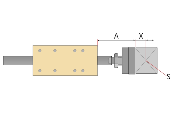
Figure 4: The max working load is a function of the pneumatic cylinder's projection (A) plus the distance to the working load's center of gravity (X). The working load's center of gravity is marked S.
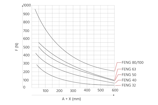
Figure 5: The max working load (F(N)) for plain bearing FENG guide units. The max working load drops as the projection (A) and distance to the working load's center of gravity (X) increase.
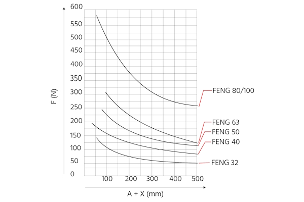
Figure 6: The max working load (F(N)) for ball bearing FENG guide units. The max working load drops as the projection (A) and distance to the working load's center of gravity (X) increase.
FAQs
What is a guided pneumatic cylinder?
A guided pneumatic cylinder is a type of cylinder that includes a guide unit to provide additional support and alignment to the piston rod, ensuring smoother and more precise linear motion.
How does a Festo guided cylinder work?
A Festo guided cylinder works by using a guide unit to manage and distribute loads, preventing the piston rod from bending or deflecting under heavy loads, ensuring high accuracy and repeatability.
Why use a guided cylinder?
A guided cylinder is used to provide better alignment, reduce side loads, and minimize wear and tear on seals and bearings, extending the lifespan of the pneumatic cylinder.
What applications require guided pneumatic cylinders?
Applications requiring high accuracy, repeatability, and where the cylinder is subjected to side or off-center loads, such as in automation and material handling, require guided pneumatic cylinders.

