


Steps To Wire an Electric Ball Valve With a Float Switch
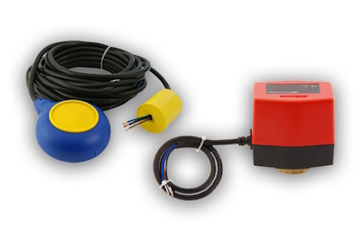
Figure 1: Mac3 float switch (left) and AW1-024DC electric ball valve actuator
Automatic liquid level control can be achieved by wiring a float switch to an electric ball valve, eliminating the need for manual monitoring. This setup is widely used in tanks, reservoirs, and other fluid systems to maintain a consistent liquid level. This article discusses how to wire a Mac3 float switch to AW1-024DC electric ball valve actuator. The control logic remains the same for other actuator models; however, wire color codes may vary, so always refer to the manufacturer’s wiring diagram before installation.
View our online selection of float switches and electric ball valves!
Step 1: Preparation
- Isolate the power supply: Disconnect the electrical source before handling any wiring. This prevents short circuits or accidental energization of the actuator during installation.
- Lower the liquid level in the tank: The float switch must be installed in a dry or partially dry condition to prevent accidental operation or water damage while wiring.
-
Check the float switch function with a multimeter: Place the multimeter in continuity mode.
- Connect one probe to COM (black) and the other to NO (blue), then tilt the float downward. The meter should beep (circuit closed).
- Move the probe from NO to NC (brown) and tilt the float upward; the meter should beep again.
This confirms the float properly switches between NO and NC contacts at its trigger points.
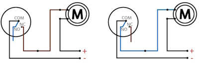
Figure 2: Wiring a MAC3 float switch to a motor
-
Check actuator operation: Temporarily connect the blue wire from the electric ball valve actuator to the negative terminal of the 24 V DC supply.
- Applying a positive signal to the brown wire should rotate the valve open. A positive signal to the black wire should rotate it closed.
This test confirms the actuator wiring and movement directions before connecting the float switch.

Figure 3: AW1-024DC wiring diagram: The blue wire is permanently connected to the negative terminal. Applying positive voltage to the black wire closes the ball valve, while applying positive voltage to the brown wire opens it.
Step 2: Wiring connections
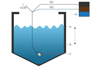
Figure 4: Wiring a Mac3 float switch to AW1-024DC electric ball valve actuator showing the high set point (A), low set point (B), and float switch (C).
When a float switch is wired to an electric ball valve, it automatically opens the valve when the tank is low and closes it when the tank is full.
- Connect the actuator’s blue wire permanently to the negative terminal of the 24 V DC power supply.
- Connect the float switch COM (black) directly to the positive terminal of the supply.
- Connect the float switch NO (blue) to the actuator’s brown wire (open command).
- Connect the float switch NC (brown) to the actuator’s black wire (close command).
- Secure all connections using crimp connectors or a terminal block. Cover with heat-shrink tubing or place inside a waterproof junction box if the installation is in a damp environment.
Control logic
- Low-level trigger (tank emptying): When the water level falls to the lower set point (Figure 4, B), the float tilts downward. COM (black) connects to NO (blue). This energizes the actuator’s brown wire, causing the valve to rotate open. Water flows into the tank.
-
High-level trigger (tank filling): As the tank fills and the float rises to the upper set point (Figure 4, A), COM (black) disconnects from NO and connects to NC (brown). This energizes the actuator’s black wire, rotating the valve closed. The inflow stops.
At any moment, only one actuator control input is energized, preventing simultaneous open and closed signals.
Step 3: Commissioning checks
- Functional check: Manually move the float through its full range. Verify that the valve opens at the low-level trigger and closes at the high-level trigger.
- Current load check: Confirm that the actuator’s current draw does not exceed the float switch’s rated load. If it does, use a relay between the float switch and actuator.
- Overflow safety check: Measure the actuator’s closing time (e.g., 16 seconds). Ensure the float switch is set low enough so that the tank can hold the extra water entering during valve closure without overflowing.
- Polarity check (for DC actuators): For DC actuators, ensure correct wiring of positive and negative terminals to prevent malfunction or damage. Polarity is not a concern for AC actuators.

