


Contactor vs Relay - Understanding The Differences And Applications
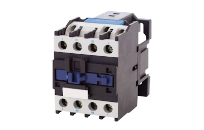
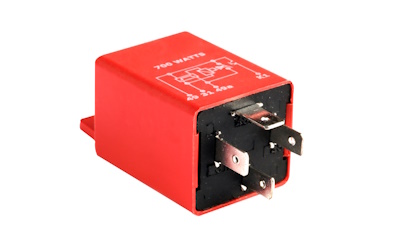
Figure 1: Contactor (left) and an electromechanical relay (right)
Relays and contactors are essential components in electrical systems, serving as critical controls for managing power circuits. Both devices operate on the same principle but differ significantly in their capacity and functionality. While relays are typically used in low-power applications to switch smaller currents, contactors are designed to handle high-power circuits, making them suitable for industrial and commercial use. This article discusses the differences between relays and contactors, highlighting their unique roles in various electrical systems and the factors for selecting one over the other.
Table of contents
View our online selection of contactors!
How to choose between a contactor and relay
Choose a relay when:
- The current is 10 amperes or below
- The voltage is up to 250V AC
- The application is single-phase
Choose a contactor when:
- The current is 10 amperes or above
- The voltage goes up to 1000V AC
- The system is either single-phase or three-phase
The circuit function is also a critical factor. A contactor is preferable if there's potential for an overload that could cause a hazardous situation should the circuit not power down correctly. However, if the low-power switching and the advanced safety features of a contactor are unnecessary, a relay usually offers a more cost-effective solution.
Note: The information provided in this article is for educational purposes only. Always ensure to review the detailed component specifications or seek guidance from a professional.
Keep reading for more in-depth information on relays and contactors.
What is a relay
A relay is an electromechanical or solid-state switch for regulating electrical current flow in low to medium power applications. It comprises a coil, contacts, and an enclosure. When power is applied to the coil, a magnetic field is created that pulls the contacts together or apart, thus closing or opening the circuit as per the relay's design (Figure 2). Consequently, this controls the current flowing to the connected electrical load. Read our relay applications article for more information on the working and wiring of industrial relays.
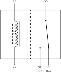
Figure 2: Relay terminals
What is a contactor
A contactor is an electromechanical switch specifically designed to manage the flow of electrical current in high-power applications. It comprises a coil, contacts, and a protective enclosure. When the coil is activated, it creates a magnetic field that pulls the contacts together, thus closing the circuit and enabling the current to flow to the load.
While relays and contactors share similar construction principles, contactors are specifically optimized for high-power applications through design choices. These features include larger contacts, better materials, more effective arc suppression, and stronger mechanical construction. The next section discusses these parameters in detail.
Relay vs contactor
Load capacity
Relays are typically utilized in lower current-level applications, generally not exceeding 15 amperes. They are suitable for managing smaller loads or as an intermediary that links a low-power control signal to a more substantial power load.
Contactors control currents exceeding 15 amperes while retaining a compact size. They are well equipped to handle extremely high currents, often in excess of 5000 amperes, and power levels above 100 kilowatts.
Materials
The contacts in contactors are generally made of highly conductive materials like copper, often with a silver or silver alloy coating to reduce contact resistance when switching high currents. They have enclosures made of plastic or metal. Metal enclosures are often used in industrial environments where higher protection levels are necessary due to harsh conditions, such as high temperatures, impacts, or the presence of corrosive materials. Plastic enclosures are also used for their insulating properties and can be found in less demanding environments.
The contacts in relays are usually made of conductive metals such as silver or silver alloys. Gold-plated contacts are often used for low power applications as gold has excellent corrosion resistance and ensures reliable operation for low-level switching. The enclosure for a relay is typically made of plastic.
Open/closed contact standards
Contactors are primarily constructed to work with normally open contacts, creating a connection when activated and breaking the connection when not powered. In contrast, relays can be designed to have normally open and/or normally closed contacts. Also, relays can have multiple contacts, enabling them to manage several circuits simultaneously. They can be configured in various ways to provide different switching arrangements, such as single-pole double-throw (SPDT) or double-pole double-throw (DPDT), to suit diverse requirements. Read our article on relay types for more details on the various types of relays based on construction and operation principles.
Auxiliary contacts
Contactors often have auxiliary contacts that can be either normally open or normally closed. These auxiliary contacts are not for carrying the main load but for additional control functions, such as signaling when a motor is running by illuminating a pilot light. Relays have very few auxiliary contacts.
Spring-loaded contacts
Due to their high loads, contactors frequently have safety features like spring-loaded contacts. This is crucial since there is a risk that contacts under high load could weld together, potentially leaving a circuit energized when it should be disconnected. Spring-loaded contacts mitigate this risk by ensuring a reliable break in the circuit. Relays handle lower power, hence they typically do not need this feature.
Arc suppression
Contactors have arc suppression mechanisms like magnetic arc suppression, which is essential due to the significant loads they control. Arc formation occurs when the contacts open or close, generating an electrical arc between them.
Magnetic arc suppression, often called arc quenching or arc extinguishing, is used in electrical circuits to reduce or eliminate the arc formed when a switch (such as a relay or contactor) opens and interrupts an electric current. The technique commonly involves creating a magnetic field that drives the arc into an area with arc chutes or splitter plates, where the arc is lengthened, cooled, and split into smaller arcs until it can be extinguished as the contacts continue to separate. This process helps protect the switch contacts from damage and prolongs the life of the device. Arc suppression is less of a concern for relays, which control lower loads; hence, this feature is not common in relays.
Overload protection
Contactors are often paired with overloads that disrupt the circuit if the current exceeds a predetermined limit for a certain duration, protecting downstream equipment from damage caused by excessive current. Also, they manage large inrush currents when starting up large motors or engaging other inductive loads. Overloads are not as commonly associated with relays.
Applications
Contactors are usually designed for 3-phase systems, while relays are typically found in single-phase applications. Contactors are frequently rated for voltages up to 1000 volts, contrasting with relays, which are commonly rated for up to 250 volts.
Figure 3: A contactor installed on an HVAC unit
Table 1: Main features of contactors and relays
| Feature | Contactor | Relay |
| Power handling | Designed to handle high currents (up to thousands of amps). | Typically handles lower currents (up to or less than 30 amps). |
| Application | Used for high-power applications such as motors, heaters, and large lighting loads. | Used for low-power applications, signaling, and control circuits. |
| Construction size | Generally larger due to robust construction to handle higher power. | Smaller, since they are designed for lower power loads. |
| Contact size/material | Larger, more robust contacts made from materials that can cope with higher power and heat. | Smaller contacts, with less demand for heat resistance and durability. |
| Arc suppression | Advanced arc suppression methods to manage higher arc energy when switching. | Less robust arc suppression, as the arcs produced are smaller. |
| Durability | Built to withstand frequent and high-current operations. | Suitable for less frequent and lower-current switching. |
| Auxiliary contacts | Often have multiple auxiliary contacts for additional control and feedback. | Usually fewer auxiliary contacts. |
| Coil voltage | Typically has a higher coil voltage range to accommodate industrial environments. | The coil voltage range can be lower, suitable for control panels and electronic circuits. |
| Protective features | Often paired with overload protection devices. | May not have built-in overload protection. |
| Cost | More expensive | Less expensive |
| Use case | Common in industrial power systems. | Common in electronic devices, small machinery, and control systems. |
FAQ
What is the difference between a contactor and a relay?
Contactors switch high-power loads, while relays are for low-power signals. Contactors are larger and more durable.
