


A Guide To Ball Valves
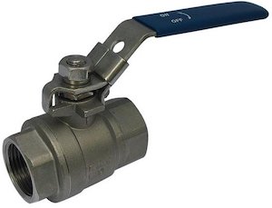
Figure 1: 2-way manual ball valve
A ball valve is a shut-off valve that uses a rotating ball with a hole to control the flow of gasses and liquids. The ball can be rotated 90 degrees (quarter-turn) with a handle or actuator to open or close the valve. Ball valves are durable, reliable, easy to use, and provide tight sealing throughout their use, even when left unused for an extended period. This article discusses the working, features, and different types of ball valves.
Table of contents
- What are the parts of a ball valve?
- How a ball valve works
- Manual and actuated ball valves
- 2-way and 3-way ball valves
- Ball valve materials
- Connection types for ball valves
- Full port and standard port ball valves
- 1, 2, and 3-piece ball valves
- Can ball valves be used for flow control?
- Special ball valves
- FAQs
View our online selection of ball valves!
What are the parts of a ball valve?
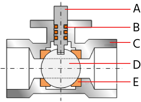
Figure 2: Ball valve diagram: stem (A), o-rings (B), housing (C), ball (D), and seat (E).
Figure 2 shows the main components of a 2-way ball valve:
- Valve stem (A): The valve stem connects the actuator (e.g., handle or actuator) to the ball.
- O-rings (B):O-rings in a ball valve are circular seals made from materials like rubber. They prevent leaks by creating a tight seal between parts, such as around the stem or seats.
- Housing (C): The housing supports all the valve's internal components and protects them from application and environmental conditions. The housing usually has openings for connecting pipes, known as inlet and outlet ports. The housing is made of strong and durable materials like brass, stainless steel, or PVC.
- Ball (D): The ball has a hole through which fluid can flow when the valve opens. This hole aligns with the valve's path, letting fluid pass through. When the bore is turned perpendicular to the flow, it stops the fluid from passing through.
- Seat (E): The seat supports and seals the ball component. Ball valves usually feature two seats. When the valve is closed, these seats create a tight seal around the ball. The upstream seat seals against the pressure of the incoming fluid, while the downstream seat prevents any leakage from escaping into the atmosphere.
How a ball valve works
- Open position: When the valve handle is turned 90 degrees, the ball rotates so that its bore aligns with the flow path. This alignment allows fluid to flow freely through the valve. In this position, the handle is parallel to the pipe, indicating that the valve is open.
- Closed position: Turning the handle back 90 degrees rotates the ball so the bore is perpendicular to the flow path, effectively blocking fluid passage. In this position, the handle is perpendicular to the pipe, indicating that the valve is closed.
While manual operation using a handle is common, ball valves can also be equipped with actuators for automated control.
Manual and actuated ball valves
Manual ball valves
Manual ball valves use a handle or lever to open and close the ball valve. They are simple and cost-effective, ideal for low-cycle applications without automation. However, they require manual operation, limiting their use in remote or hazardous areas. ISO-top ball valves (Figure 5) have a standardized mounting flange according to ISO 5211 for mounting an electrical or pneumatic actuator.
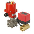
Electric ball valves
Electric ball valves use an electric actuator to automatically open and close the valve. They are suitable for applications needing precise flow management and integration with control systems. They offer high accuracy but depend on electrical power, making them more expensive and complex to install and maintain. Electric ball valves are commonly used as zone valves in heating systems.
It's essential to consider the response time while selecting an electric ball valve. In emergencies, a quick response can prevent accidents and reduce the risk of damage to equipment and personnel. Other important parameters to consider are torque requirements, power consumption, and compatibility with existing control systems. Learn more in our article on electric ball valve overview.
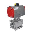
Pneumatic ball valves
Pneumatic ball valves, actuated by compressed air, are ideal for fast-cycling applications due to their rapid response time. They are inherently safe for use in explosive or hazardous environments, as they do not involve electrical components. This makes them a preferred choice in industries like oil and gas. Also, pneumatic actuators provide high force and torque, suitable for larger valves or applications requiring significant actuation power. However, they require a compressed air system, which can add to infrastructure and maintenance needs. Learn more in our article on pneumatic ball valve overview.
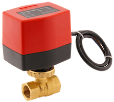
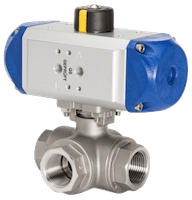
Figure 3: 2-way electric ball valve with an integrated relay (left) and a 3-way pneumatic ball valve (right)
2-way and 3-way ball valves
Common ball valves have two or three ports, known as 2-way and 3-way configurations.
- 2-way: In a 2-way ball valve , the flow direction is straight, from input to output. 2-way ball valves are used for basic on/off fluid control.
-
3-way:3-way ball valves have three ports. They come in either an L-port or T-port configuration. These designations refer to the internal bore structure, which dictates the direction of the media flow.
- The L-shaped bore can direct flow between two paths, making it suitable for diverting applications. The T-shaped bore can connect or isolate three paths, allowing for more versatile flow control, such as mixing or distributing fluids.
Ball valve materials
Housing materials
Stainless steel, plastic, brass, and cast iron are the various housing materials for ball valves. Each material has different properties, so choosing the right one ensures optimal system performance, safety, and cost-efficiency. Read our article on ball valve materials for more information on the media compatibility, temperature, and pressure tolerance of ball valve housing and seat materials.
Table 1: Stainless steel vs brass, plastic, and cast iron ball valves
| Material | Advantages | Disadvantages |
| Brass | Durable, suitable for most applications | Sensitive to dezincification |
| Stainless Steel | Very abrasive resistant, inert, corrosion resistant | Higher cost, often more torque is needed to rotate the ball |
| Plastic | Cost-effective, not prone to corrosion | Shorter lifespan, limited pressure and temperature ranges |
| Cast Iron | Strong, suitable for long-term high-pressure applications | Prone to rust and corrosion, heavy, brittle |
Seal materials
Ball valves with PTFE (Teflon) seats are commonly used. However, ball valve seals can also be made of metals or other synthetic materials like PA (polyamide), EPDM (Ethylene Propylene Diene Monomer), and FKM (Fluoroelastomer). For more information, refer to our chemical resistance of materials guide.
Connection types for ball valves
Ball valves can be connected to pipes in several ways, making them versatile for various applications. Read our ball valve connection types article for more information on the end connection types for different ball valve types.
Table 1: Ball valve connection types
| Connection type | Description | Applications | Advantages | Limitations |
| Threaded | Uses male and female threads; available in straight and tapered forms. | Residential plumbing, small-scale industrial systems (pipe diameters < 101 mm). | Cost-effective, easy to install, maintain, and replace. | Prone to leakage in larger diameters; may require sealants. |
| Flanged | Utilizes solid metal plates with bolt holes for secure attachment. | Industrial settings, especially for valves > 101 mm. | Easy to install and remove; suitable for high-pressure applications. | More expensive, especially in larger sizes. |
| True union | Allows valve assembly removal without disturbing the piping system. | PVC piping systems needing frequent maintenance or component replacement. | Easy disassembly and reassembly; extends valve lifespan. | Typically more expensive and bulkier than threaded ball valves |
| Glued sleeve | Uses adhesive for a permanent bond between valve and pipe. | Plastic piping systems, residential plumbing, and irrigation. | Provides a permanent, leak-proof seal. | Not suitable for high-pressure applications; no flexibility for maintenance. |
| Hose pillar | Features a barbed end for flexible hose connections. | Low-pressure applications, such as garden hoses and temporary setups. | Simple and quick to install. | Limited to low-pressure applications; may require clamps for a tight seal. |
Full port and standard port ball valves
Ball valves can be full or standard (reduced) ports based on their bore size.
- Full port ball valves have a bore diameter that matches the pipe size, providing minimal flow restriction. They cause a very low pressure drop and can be easily cleaned (ideal for pigging). However, they are costly compared to standard port ball valves.
- Standard port ball valves have a slightly smaller bore. They have higher velocity, energy loss, and pressure drop than full port ball valves. However, they are compact and less costly.
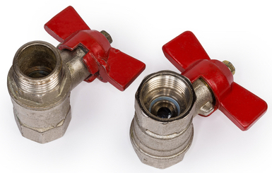
Figure 4: Full port (left) and standard port (right) ball valves
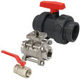
1, 2, and 3-piece ball valves
Ball valves come in 1, 2, or 3-piece designs.
- 1-piece ball valve: This valve has a solid one-piece design. It is compact and suitable for low-pressure residential applications, such as plumbing systems.
- 2-piece ball valve: A 2-piece ball valve has two parts. It can be easily disassembled without cutting the pipe, allowing easier maintenance. The valve is versatile, with various sizes and pressure ratings. It is commonly used for industrial applications where frequent servicing may be required.
- 3-piece ball valve: A 3-piece ball valve has three parts that can be easily assembled and disassembled. The design allows for customization, as individual components can be replaced. It is ideal for high-pressure applications and is used in chemical processing, oil and gas, and water treatment. However, 3-piece ball valves are costly.
Read our 1,2,3-piece ball valve article for more details on the construction and design of each type.
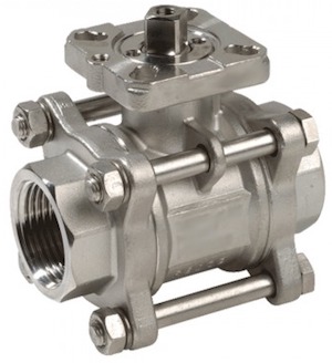
Figure 5: Stainless steel 3-piece ball valve
Can ball valves be used for flow control?
Ball valves typically function as shutoff valves to control the flow of liquids or gasses in a piping system. They are not ideal for precise flow control.
Characterized ball valves are modified ball valves explicitly designed for fluid control. The bore shape in a characterized ball valve can be customized to 'V,' 'U,' or parabolic shape to suit the application's specific requirements. They control and modulate the flow, offering stability and precision. For more information, read our articles on characterized ball valve and v-port ball valve.
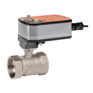
Figure 6: Belimo characterized ball valve for HVAC applications
Special ball valves
- Vented: A vented ball valve has a venting mechanism to release trapped pressure, preventing potential damage or hazards. Read our vented ball valve overview article for more details on the design, working, and applications of vented ball valves.
- Modulating: A modulating ball valve can adjust to any position between fully open and fully closed. This allows precise flow regulation to control parameters such as temperature, level, or concentration. It is typically automated with an electrical actuator and a feedback system to provide real-time position information.
- 90-degree ball valves:90-degree ball valves connect residential and commercial water and gas supply lines to fixtures perpendicular to the supply line. They enable quick shutoff and isolation for maintenance or emergencies. Read our right angle ball valve overview article for more information.
- High pressure ball valves:High pressure ball valves are used for hydraulic and heating oil applications up to 500 bar (7,250 psi). They are operated with a handle and provide unobstructed flow due to the full-bore design. Read our hydraulic ball valve article for more information.
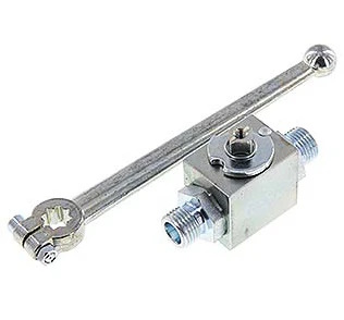
Figure 8: 2-way hydraulic ball valve for high pressure applications
FAQs
Can a ball valve be partially open?
A ball valve is not recommended for throttling as it can cause uneven wear, vibration, and noise. Use characterized ball valves for throttling.
Where is a ball valve used?
Ball valves are used in pipelines for on/off control in industries, residential plumbing, and irrigation systems due to their quick operation and tight sealing.
Can a ball valve control flow?
While a ball valve can control flow, it is not ideal for precise flow regulation. It is best suited for applications requiring full open or closed positions.
Why do you need a ball valve?
Ball valves are needed for their reliable, quick shut-off capabilities, minimal pressure drop, and durability, making them ideal for various fluid control applications.
Which is better, brass or plastic ball valves?
Brass ball valves are more durable and heat-resistant, suitable for high-pressure and temperature applications. Plastic valves are corrosion-resistant and lightweight, ideal for chemical exposure.
When is a ball valve open?
A ball valve opens when the handle is in line with the pipe and closes when it is perpendicular to the pipe. It only needs to be rotated 90 degrees.
Can ball valves fail?
Yes, a ball valve can fail. Common failure types are a damaged seal (valve won't seal 100%) or debris entering the valve (valve won't move).
What can a ball valve be used for?
A typical ball valve functions as a shut-off valve. Use a characterized ball valve, such as a v-port ball valve, for precise flow control.


