


How To Use a Multimeter
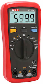
Figure 1: Multimeter
A multimeter is a device used to measure multiple parameters of an electric circuit like voltage, current, and resistance. The device is made up of a digital or analog meter, batteries, resistors, and other circuitry, which ensure the measurement of several electrical quantities with very high accuracy and speed. It is one of the most common tools used by technicians, students, and engineers across the globe. Hence, familiarizing the components of a multimeter and how to set it for various measurements has become inevitable while dealing with an electrical circuit. This article covers everything you need to know about how to use a multimeter.
Table of contents
- Uses of multimeter
- Types of multimeter
- Multimeter components
- Using a multimeter
- Precautions while using a multimeter
- FAQs
View our online selection of clamp meters and multimeters!
Uses of multimeter
A multimeter is used to troubleshoot electrical problems on motors, circuits, power supplies, and switches. It is the most common tool used by technicians to troubleshoot electrical issues. A few examples of use cases are:
- To test a questionable battery, connecting the multimeter leads and measuring the DC voltage across, is a quick and efficient way to decide whether it is dead, good, or somewhere between. Read our article on testing a car battery using multimeter for a step-by-step guide.
- While assembling different parts of a project or product, it is common to work with a bundle of wires of the same color, in which case a multimeter can be used to test the resistance of each one which helps to distinguish one from the other.
- When in doubt regarding which pin is ‘live’ while checking an AC outlet, a multimeter can be used to determine the voltage coming out of the point and thereby check if it is live.
- While working on electronic boards, it is common to worry if a chip has overheated or a capacitor is faulty or not, and a multimeter can be used to check whether the temperature is within limits.
- Coaxial cables can be checked for their continuity using a multimeter.
Types of multimeters
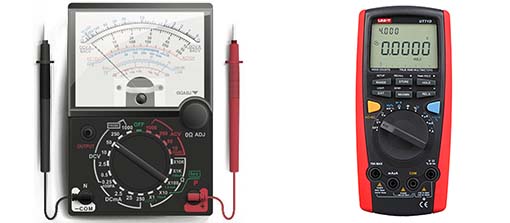
Figure 2: An analog multimeter (left) and a digital multimeter (right)
A multimeter is broadly classified into analog and digital, the main difference being in their respective display units.
- Analog multimeters have a needle pointer to display readings, as seen in Figure 2. They are ideal for applications with rapidly changing values as it shows values more clearly when compared to their digital counterparts.
- Digital multimeters output a numeric number on their display. They are more common due to their high precision when compared to their analog counterparts.
Multimeter components
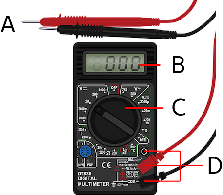
Figure 3: A digital multimeter with its probes and front panel: probes (A), display panel (B), selection knob (C), and ports (C).
The main components of a multimeter are shown in Figure 3. Each of the labels are explained as follows:
- Selection knob (C): The knob comes with an arrow pointer at its end to choose the parameter being measured (like the voltage, current, and resistance).
- Display panel (B): The display is a liquid crystal display (LCD), which can show up to four digits under normal circumstances, and also has the provision to display a negative sign.
-
Ports (D): There are three main ports on the front panel of a multimeter:
- COM symbolizes COMMON and is usually used to connect the ground or negative part of the circuit.
- VΩmA enables the measurement of voltage, current (up to 200mA), and resistance.
- 10A is the special port used to measure large currents (typically greater than 200mA).
- Probes (A): Typically, a multimeter unit comes with two insulated probes (a red probe and a black probe) to establish an electrical connection between the device under test (DUT) and the multimeter. The plug of the red probe is connected to the VΩmA port, and that of the black probe is connected to the COM port, while their leads are connected to the positive and negative terminals of the device under test (DUT). Other than the color, there is no difference between the red and black probes.
Using a multimeter
The front panel of the multimeter has various functionalities, as seen in Figure 4.
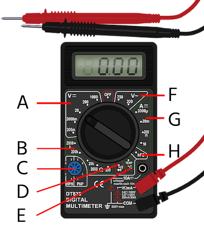
Figure 4: Using a multimeter for testing: DC voltage (A), mounting space for emitter, base, and collector terminals of a transistor (B), resistance (C), continuity check(D), temperature (E), AC voltage (F), Current (G), and transistor gain (H).
How to measure voltage with a multimeter
- Rotate the knob and select a value under which the designated voltage value may lie.
- Connect the lead of the red probe to the positive terminal and the black probe lead to the negative (or ground) terminal.
- Ensure the correct range to be measured is selected. A general rule of thumb is to set to the highest range first, and then change to the next lower range if needed.
- The display will display the voltage across the leads.
For example, to check if a mobile phone’s battery is at fault, connect the battery to the red and black probes, twist the knob, and select the 20V value (because the anticipated value of the voltage across the mobile phone battery is around 5 volts, hence a higher value has to be chosen from the panel under which the estimated voltage falls). This may require some trial and error.
Make sure to select from the range of DC voltages. If the voltage under consideration is AC, as in the case of an electrical plug inside the house, twist the knob and select V~ (which symbolizes an AC voltage measurement).
How to measure current with a multimeter
- Twist the knob and select from the ranges of current displayed on the panel.
- Connect the red probe to the 10A jack in case the current being measured is greater than 200mA.
- Ensure the correct range to be measured is selected. A general rule of thumb is to set to the highest range first, and then change to the next lower range if needed.
- The display shows the current across the leads.
How to measure resistance with a multimeter
- To check the value of a resistor, connect the resistor across the red and black probes, twist the knob so that it points to one of the resistance values across the front panel (start with the highest value).
- The selected value on the panel should always be greater than the resistor value that is being measured, so apply a little bit of trial and error in choosing the knob pointer. But either way, the resistance value is obtained much faster with more accuracy when compared to the conventional manual method of ‘BBROY’ (using color coding in resistors to determine their resistance values).
- The display shows the resistance value measured across the leads.
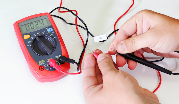
Figure 5: Measurement of resistance using a multimeter
Multimeter continuity test
The probes in a multimeter can be used to test whether there is a viable connection between two points in a circuit. This function is especially helpful while debugging a circuit and checking for connection errors. A fuse can be checked by connecting it across the probes in continuity mode, and if it results in a beep sound, the fuse is good to go. For a detailed guide on testing a fuse please read our article on testing a fuse with a multimeter.
- Twist the knob and select the symbol corresponding to a propagating sound wave on the panel under which the device enters the continuity check mode.
- In this mode, when both probes touch each other, a beep sound indicates a closed connection.
- Touch a probe to point A and the second probe to point B and if a beeping sound is made it shows they are connected.
- The display panel shows the resistance across the points being tested.
Test transistor with multimeter
A transistor is tested by a multimeter to check for faults or the value of its forward gain (hfe).
- Twist the knob of the multimeter and set it to ‘hfe’ point.
- Connect the three terminals of the transistor on the socket provided for transistor on the multimeter’s front panel.
- Note the value of ‘hfe’ displayed on the multimeter.
- Compare the experimental value with the value provided in the transistor’s datasheet to check if it is a match.
- Alternatively, check the individual junctions of the transistor for continuity as discussed in the previous section.
Precautions while using a multimeter
- It is advisable to anticipate the signal to be measured, and set the range on the device accordingly to avoid overpowering and damaging the multimeter.
- To extend the battery life of an electrical multimeter, turn off the multimeter when not in use.
- While using the red and black probes of the multimeter, always make sure to hold the gripped portion and not beyond this area to prevent getting electric shocks while measuring large voltages.
- After use, try to encapsulate the multimeter and probes in their respective cases to avoid mechanical or electrical damage.
- If the multimeter is kept for longer periods without any operation, make sure to remove their batteries to prevent corrosion.
FAQs
Is an ammeter a type of multimeter?
An ammeter measures the electric current flowing through a circuit, whereas a multimeter can do more, like the voltage, current, & resistance measurements.
What type of multimeter do I need?
The choice of multimeters depends solely on the application. A few pointers are the parameters to be measured, ease of usage, cost, and the manufacturer.
What is the difference between a voltmeter and a multimeter?
A voltmeter can only measure voltage, while a multimeter can measure voltage, resistance and current.

